The DCS shall sample each process state variable with an identifier, a time
stamp and an error identification in case of error.
Note: Units, name, Quality of Service parameters and description of the
state variable are not required in the sampled data as they are defined in
the DSC SDF.
SWC-DCS-0020: Raw data conversion
The DCS should apply the conversion from raw data to engineering data
(scaling) as near as possible to the source of the data.
SWC-DCS-0021: Time stamping latency
The DCS shall time stamp state variables as close as possible to the source
of data.
SWC-DCS-0022: Calibration factor
The DCS shall provide the capability to configure the calibration factor and
conversion formula applied to each state variable.
Note: Identify and capture relevant Device properties/features
SWC-DCS-0023: State variable data transmission
The DCS shall provide the capability to transmit both raw data and
engineering data to the GCS Core systems.
SWC-DCS-0024: Telemetry data archiving
The DCS shall archive telemetry data only in the case that a circular buffer
is required to manage high throughput telemetry.
Note: All the GMT telemetry data is stored and archived by the telemetry
service outside the DCS.
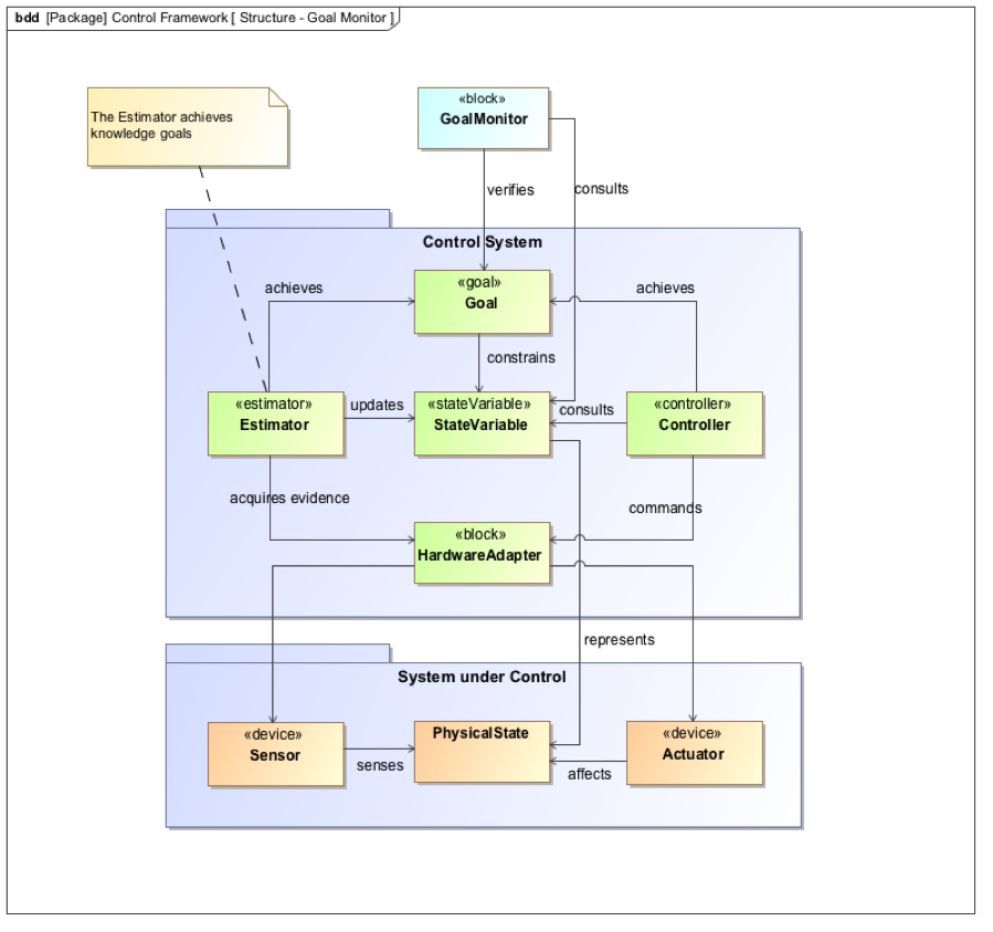
The above diagram represents an overview of the control, supervision and
monitoring functions and their relation with state variables.
ops_state State Variable
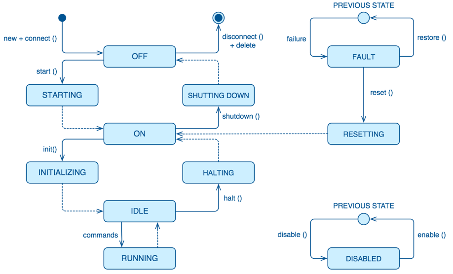
The ops_state state variable represents the operational state of a Component
[reword]. A set of states addresses the distributed nature of the component
and its life cycle management. Figure 5‑1 shows the ops_state state
machine. Only the description of each state is shown. Details about entry
actions, transitions and activities are omitted in this diagram.
Table%s provides the specification of the
Controller state machine. The specification defines what actions to implement
in every state or transition, however in some of the states each Controller
implements its own specific logic.
Initial pseudo state. The Controller is not operational because it
has not been created yet. The Controller cannot inform this state
as it is not running. In this state the software is not running and
controlled equipment is not available.
TERMINAL
Final pseudo state of any Controller. It is equivalent to the
initial state. A final state cannot have any outgoing transitions.
PREVIOUS STATE
This pseudo state is a UML formalism that, within a composite
state, memorizes the previous sub-state that was active prior to
leaving the composite state. This is used when a Controller
enters the FAULT or DISABLED states.
OFF
The Controller is created, loaded and initialized with the
default properties, but part of the software and hardware is not
initialized and configured yet. All the external Devices
controlled by the Controller shall be switched-off. In this
state the Controller is not ready for operation, but it is
possible to perform tests and diagnostics activities, specially
related to the communication capabilities. The Controller is in
a static state waiting for events.
STARTING
The Controller is being started. Any external equipment
controlled by the Controller is being switched on. In some
cases, the power supply is shared with other Controllers. It
also performs the starting procedure which can include:
Obtaining configuration properties from the configuration
system
Obtaining references to the required device or bus drivers
Starting telemetry samplers, alarm rules, etc.
Checking communication with the connected Devices (e.g., a
motion drive)
Other activities that depend on the specific Controllers and
Devices connected to it.
ON
The Controller and the connected Devices are already properly
initialized and configured. When connected, and depending on
the Controller, external equipment shall be in safe state (e.g.,
brake engaged, motion drives disabled, locking pins inserted).
This state can be the final state after a reset or after a power
failure.
INITIALIZING
While the Controller is in this state the necessary procedures
required to make the controller ready to receive operation
requests (e.g., find fiducial marks) are executed.
RUNNING
The Controller is running and can be idle or serving an
operation request. In this state the Controller can receive new
commands or is accepting data in its data inputs and sending
data through its data outputs.
SHUTTING DOWN
Back to OFF state (different for each Controller: power off
Devices)
HALTING
Back to ON state (different for each Controller: Engage brakes,
disable drives)
FAULT
The Controller has detected a severe failure and is waiting for
an event to occur (e.g., operator input) to correct such
situation.
RESETTING
Return to a safe and known state. For example, when the
Controller has entered into a FAULT state, due to the ISS
triggering an interlock condition (which can disable drives,
remove power, etc.), a reset command must be sent to the
Controller.
DISABLED
In this state the Controller rejects attempts to perform any
control action. This is especially important with Controllers
connected to Devices. In this state the Controller does not
send demands to the equipment requesting motion or a change (a
message is sent to the client indicating that the Controller is
disabled). Note that the Controller is ready and it will answer
requests that ask for some status, but it will not execute any
commands that lead to actions on connected Devices. This state
can be reached from any state, and when enabled, will return to
the previous state.
SWC-DCS-0079: DCS State Machines
Each DCS component shall implement ops_state state machine.
SWC-DCS-0080: State Machine monitoring
Each DCS component shall send an status message for each state transition to
the GCS.
sim_mode State Variable
Controllers that interface with hardware support specialized operation modes,
on-line and simulated:
In real mode, controllers try to detect and setup the hardware elements
connected to them during startup. If some of the required hardware
devices are not available the controller will transition to fault mode.
This is the default mode when the system is deployed for operation at the
observatory.
In simulation mode, controllers will setup the I/O framework in simulation
mode. Communication messages with the hardware will be logged, but will
not be sent to the hardware devices. Hardware devices will not be powered
up during the startup sequence. This mode is intended to be use during
development when the hardware is not yet available or is available
partially. It also enables controller debugging once the hardware is
integrated.
SWC-DCS-0081: on-line operation mode
DCS shall support the on-line operation mode
SWC-DCS-0082: simulation operation mode
DCS shall support the simulation operation mode
control_mode State Variable
GMT distributed components shall support two operation modes, standalone and
integrated:
In integrated mode, components will try to connect with the observatory
services. If the services are not available the component will stop its
startup sequence. This is the default operation mode when components are
integrated and deployed in the observatory or integration simulator.
In standalone mode, components do not try to connect to the observatory
services (e.g., log and alarms send their messages to the console or a
file). This operation mode is intended to be used during initial component
development or when network services are not available.
SWC-DCS-0083: Normal operation
The DCS shall always be in integrated mode during normal operation
SWC-DCS-0084: Standalone mode
Use of local standalone mode should be minimized as much as possible.
SWC-DCS-0025: DCS specific user interface elements.
The DCS shall provide specialized user interface elements when the basic set
is not adequate for an efficient operation of the system under control
(reword).
Note: The GMT “User Interface Framework” (ui_fwk) provides visualization
components that target general use cases. They may be appropriate for
general engineering and basic operation. However with the DCS is controlling
a complex subsystem specialized user interface components may need to be
deployed.
TBA: [specific engineering interfaces, specific operation interfaces]
Data Processing (draft)
SWC-DCS-0026: Data processing function
The DCS shall implement the data processing functions required to operate
the system under control.
High-Level Operations (draft)
SWC-DCS-0027: Sequencing
The DCS shall implement sequencing functions to allow to operate the from
the sequencing tools.
Note: the contents of the sequencer commands per DCS shall be defined.
SWC-DCS-0028: Operation workflows
The DCS shall implement diagnosis functions to characterize non-nominal
behavior of the system under control or other DCS components.
SWC-DCS-0029: Operation commands
The DCS shall implement commands that implement the required state changes.
Diagnosis (draft)
SWC-DCS-0030: Diagnosis function
The DCS shall implement diagnosis functions to characterize non-nominal
behavior of the system under control or other DCS components.
Note: Diagnosis functions are necessary with the operational complexity of
the system makes hard to understand the behavior of the system under nominal
and non-nominal operations.
Calibration
SWC-DCS-0031: Calibration function
The DCS shall provide calibration functions when the operation of the system
under control requires parameters that have to be obtained after the
execution of measurements.
Integrity (draft)
SWC-DCS-0032: Active alarm status
The DCS shall identify and monitor the CSS alarm conditions and generate an
alarm event when these conditions take place.
Life-cycle (draft)
SWC-DCS-0033: life-cycle requirement
The DCS master supervisor shall coordinate the life-cycle of the DCS
components.
The DCS shall provide descriptions of the devices under its control. These
descriptions should capture the information relevant to perform the control
functions and to operate the Devices. The metamodel specifies the features
(e.g. vendor, model, location) necessary to model a Device.
SWC-DCS-0039: Device calibration data provenance
The description of the devices shall include information about the serial
number and location of Devices that can be exchanged so the provenance for
the calibration data can be ensured.
Alarms
The purpose of the alarm system is to provide information to the operators for
fault diagnosis and correction. The GCS Alarm Service implements an
observatory wide fault management strategy to assess and manage the overall
health of the system.
SWC-DCS-0040: Active alarm status
The DCS shall identify and monitor the CSS alarm conditions and generate an
alarm event when these conditions take place.
SWC-DCS-0026: Active alarm status
The DCS shall transmit any changes in the status of alarm conditions.
SWC-DCS-0027: Alarms and operating state consistency
The DCS shall take into account the operating states of the CSS when
monitoring alarm conditions.
Note: This is needed to avoid sending alarms when they are not significant
for a given operation state.
SWC-DCS-0028: Alarm event information
An alarm shall contain:
A timestamp
A severity
A value
An alarm description
Alarm state
Error and Status Logging
The logging function enables to record the history of events, whether normal
or abnormal, surrounding the GMT operations. Log events are intended for view
and access on an operation console, and stored in a persistent database.
SWC-DCS-0029: Log event information
A log message shall include:
A time stamp
A process identifier according to the naming scheme
A text explaining the event
A message level (debug, info, warning, error).
SWC-DCS-0030: Log events
The DCS shall record and transmit the following messages to the logging
system:
Each timing, DCC, PLC or embedded system events or state changes.
Each change of configuration properties
Each transitions in operating states
Each command sent by GCS to the DCS
Each state variable validity change
Each actions done locally by operators
Any error shall be detected and an error message shall be generated and
communicated to the GCS core systems.
Configuration
SWC-DCS-0031: Configurable properties
The DCS shall be designed to be configurable by means of a set of
properties.
Note: The specification of the configurable properties of a DCS is captured
in the DCS System Definition Files (SDF).
SWC-DCS-0032: Configuration parameters
The DCS shall provide the capability to modify any configuration property
with minimum disturbance to the correct operation of the CSS
SWC-DCS-0033: Properties Configuration
The settings which are expected to be changed, however rarely, in course of
the CSS lifetime, should be made configurable without additional program
recompilation and, preferably, without program restart.
Computing Resources Management
SWC-DCS-0034: Remote control functions
The DCS shall provide remote control functions (e.g. reboot, configure,
start, stop, switch to standalone/integrated control mode).
Note: Remote control functions shall comply with the safety rules of the GMT
site.
SWC-DCS-0035: Monitoring function
The DCS shall provide the capability to monitor DCC functions and equipment.
SWC-DCS-0036: Equipment to be monitored
The DCS shall monitor at least:
DCS hardware (DCC, PLC) and software
Device Controllers
Fieldbus networks
Interface with GCS
SWC-DCS-0037: Monitored equipment status
The DCS shall provide the operational status (operational, partially
operational or not operational) of any monitored equipment
SWC-DCS-0038: Equipment performance monitoring
The DCS shall provide the capability to monitor the performance of the DCS
equipment.
Note: Performance information such as field bus status, CPU load and memory
usage or network bandwidth utilization shall be recorded.
SWC-DCS-0039: Monitoring function health
The monitoring function shall include self-tests and live tests.
The DCS shall be able to autonomously maintain safe operation of the CSS
Devices in case of loss of communication with GCS systems.
[Add reference to ISS]
[Add some guideline for safety, address black-channel (TwinSafe) design]
SWC-DCS-0056: Software Safety
The DCS shall not be the ultimate responsible of the safety of the CSS, the
system under control or persons.
SWC-DCS-0057: Limit Protection
The DCS shall have built-in absolute-limit protection to prevent errors.
SWC-DCS-0058: Limit Protection
The DCS shall have time-outs to ensure correct operation in case of GCS
failure.
SWC-DCS-0059: Non-assumption strategy
The DCS components shall avoid any assumption about the status of the CSS
equipment or the plant during the start-up process or normal operation.
Note: Although the DCS records the status of the equipment when it was
powered off, human intervention may have change the configuration of the CSS
equipment.
A set of software packages, named GMT Software Development Kit (devkit), is
distributed by GMTO for the development, test and operation of the DCS. This
package includes the required Common Frameworks and Observatory Services
distribution.
SWC-DCS-0060: GCS Simulator / early CORE / eCORE
The DCS shall use the GCS Simulator as a tool for DCS software development,
support, integration, factory acceptance test and site acceptance test.
SWC-DCS-0061: GDK version
The DCS shall use the latest GDK system version.
SWC-DCS-0062: DCS communication with GCS core systems
The DCS shall use the GMT Core Framework for the communication to/from DCS
Controllers and Supervisors.
Operating Systems
SWC-DCS-0063: DCC operating system
The Operating System for the DCC is Linux, Fedora 21 or later (TBC).
Note: Current prototypes are running in this platform.
Programming Languages and Tools
SWC-DCS-0064: Software version control tool
The software version control tool shall be git and github shall be used for
collaboration.
SWC-DCS-0065: PLC-based DCC programming language
The PLCs shall be programmed using IEC 61131-3.
SWC-DCS-0066: PLC-based DCC motion control
The PLCs motion functions shall be implemented using the PLCOpen Motion Control standard.
SWC-DCS-0067: PLC-based DCC communications
The PLCs shall implement and OPC UA server to enable communication from/to
the DCC Master Supervisor.
SWC-DCS-0068: PLC-based DCC software
The PLCs shall be programmed with the engineering software TwinCAT v3.0.
SWC-DCS-0069: PC-based DCC software
The DCS shall use the GDK software and environment to develop and test the
PC based DCC software.
SWC-DCS-0070: PC-based DCC fieldbus master
The DCS shall use the igH etherCAT master in order to acquire the process
image of the field devices connected to the fieldbus.
Note: The I/O Framework provided by GMTO provides a simplified way of
accessing the fieldbus process image.
SWC-DCS-0071: GCS SDK version
Fast controllers shall be programmed using the latest version of GCS SDK
distribution.
SWC-DCS-0072: Middleware agnostic
DCS components shall be independent of the communication middleware used.
SWC-DCS-0073: Distributed middleware transport
Nanomsg (TBC) shall be used for the communication between distributed
components.
Note: The GMT Core Framework provides independence of the middleware and is
the recommended way of implementing distributed communications.
The serialization/deserialization of transmitted packages shall be done
using MessagePack (TBC).
Note: The GMT Core Framework provides independence of the serialization
format and is the recommended way of implementing distributed
communications.
SWC-DCS-0075: Programming languages
The programming languages that can be used in the DCS software development are:
ANSI C++ cxx11 (TBC) for performance sensitive application programming in the DCC
ANSI C c99 (TBC) for driver programing in the DCC
Python 2.7/3.x (TBD) for general programming
Javascript /Coffeescript for graphical programming and modeling
IEC 61131-3 for PLC programming
Note: More specific rules should be provided. Check current code generators
and provide recommended implementation based on type of component.
SWC-DCS-0076: User interface components
User interfaces components shall be developed according to the W3C Web
Component standard.
Note: Google Polymer provides a compliant Web Component implementation. The
GMT UI Framework (ui_fwk) provides reusable components to implement user
interfaces
Modeling Requirements
System Definition Files (SDF) are used to capture the formal specification of
the DCS. Section nnn provides additional requirements on SDF. As SDF play a key
role in the specification, testing and validation of the DCS architecture. SDF
related life-cycle requirements are defined below.
SDFs are written in a Domain Specific Language (DSL). A DSL is a computer
programming language of limited expressiveness focused on a particular domain. A
DSL facilitates productivity and communication with domain experts and DSL
stakeholders. SDFs are ASCII files that are parsed and stored in the semantic
model database and processed for consistency and completeness. They are hosted
in the GMTO central software private repository in Github, for access by DCS
developers and revision control.
The concrete syntax of the SDFs is provided by the DSL, while the semantics are
given by a set of models (metamodels) following the Object Management Group Meta
Object Facility architecture.
[add graphic to explain this]
The GDK provides tools for:
DCS component skeletons and scaffolding generation
Subsystem build dependencies specification
Test procedures and test data generation
Stage-gate document generation
Project progress reporting
Subsystem deployment
Interface document generation
The SDFs are one of the deliverables of the DCS development phases. More
information on the SDF lifecycle and contents is available in DCS Specification
Workflows document (GMT-SWC-REF-0000).
SWC-DCS-0077: SDF definition
The SDF of DCS component shall include the following information:
DCS unique identification
Commands list
Alarm list
Property list
Control Data Inputs and Outputs
Configuration property lists
DCS constant values
Default values (“factory settings”) for run-time configuration used for
DCS start-up
Physical (raw) signals list (I/O) [equivalent to data_inputs]
Processed/converted signals list [equivalent to data_outputs]
Telemetry monitor list
Logging messages list
Definition of the DCS state variables and corresponding state machines
when applicable.
Definition of the DCS user interface components
Description of every component feature. [???]
Note: The formal specification of the SDF DSL is defined by the GMF metamodel.
[TBD] Add example?
[Add requirements about SDF validation, test generation and test execution?]
SWC-DCS-0077: Graphical modeling
SysML shall be used in the graphical description of the DCS designs.
Note: Although SDF provide a formal definition of the DCS that can be
validated and it is used to drive the development of the system, graphic
representations are useful to present high level views of the system
structure and behavior (state diagrams, activity diagrams, internal block
diagrams).
The DCC (Device Control Computer) is a standardized computer specified by GMTO
to be used in the deployment of the DCS. The DCC is connected to the GMT Control
Network (GCN).
Each DCC host the software components that implement the functional and physical
part of the control and data acquisition functions of the CSS devices, i.e. the
Controlled Subsystem Plant – CSP in the Figure 3‑1.
Each DCC includes a processor and an interface to the I/O modules required to
connect to hardware Devices.
I/O interfaces are either I/O adapters within the DCC (e.g. detector controller
interface cards), or use a field bus to connect with remote I/O modules (i.e.
Motion drives or discrete I/O signal interfaces).
Two types of DCCs are supported:
PC-based DCCs Intel-based Industrial Computers (PCs) running Linux with real
time extensions (RT_PREEMPT) are used in the following use cases:
High bandwidth telemetry is required
The DCS has to be integrated with the low latency network.
High computing performance is required.
Implementing complex operation scenarios is required
Control loops or data acquisition rates are faster than 100 Hz.
PLC-based DCCs Programmable Logic Controllers (PLCs) are used in the following
use cases:
The bandwidth necessary for telemetry is low.
Simple supervision, coordination or operation scenarios.
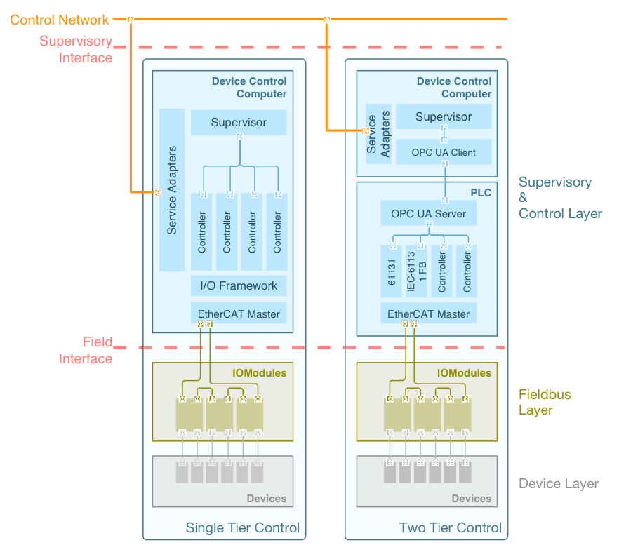
When PLC based DCCs are used a Master Supervisor is deployed in a PC-based DCC
that communicates with the PLC(s) using OPC UA. The procurement of this DCC
Master Supervisor depends on the procurement agreement and may be provided by
GMTO if the DCS provider is not familiar with the technologies used for DCS /
GCS integration. The Figure below shows an example of this arrangement.
PC-based DCS shall use Device Control Computers (DCC) based on Intel
industrial computers with PCI Express bus system and adequate interface to
fieldbus and GCN.
SWC-DCS-0112: DCC standard products
PC-based DCC, I/O Modules, terminal blocks and field buses shall be selected
from the GMT Software and Controls product catalogue. (GMT-SWC-REF-00000)
The interface between the DCC (both PLC and PC based) and the field Devices
shall be the EtherCAT fieldbus.
SWC-DCS-0094: DCS fieldbus layout
The first IO Module of the DCS fieldbus shall be installed in the GMT
Electronics room. The rest of the fieldbus IO Modules shall be installed in
the Enclosure building SECs or smaller boxes when the performance
requirements for the electrical signal path requires it.
SWC-DCS-0095: DCS fieldbus cabling
The cabling between the first IO Module of the DCS and the rest shall be
optical fiber. GMTO provides fiber links between the electronics room and
the enclosure building as part of the GCN. The cabling between the field IO
Modules shall be Ethernet UTP CAT 6 (TBC).
SWC-DCS-0096: DCS cable redundancy
The fieldbus layout shall be designed to support cable redundancy as stated
in EtherCAT protocol.
Position, Velocity and Torque control loops are
implemented on a motion drive. This mode is recommended
for single degree of freedom controllers with single or
dual encoder feedback. In this mode encoder feedback is
connected to the drive.
P-VT
The Position control loop is implemented in the DCC,
while the Velocity and Torque loops are implemented in
the drive. This mode is recommended when the position
feedback cannot be connected directly to the drive.
PV-T
The Position and Velocity control loops are implemented
in the DCC, while the Torque control loops is
implemented in the drive. This mode is necessary when
several actuators act on the same axis.
Note: Motion drives are assumed to comply the IEC 61800-7-201 and IEC61800-7-301
mapping to EtherCAT.
SWC-DCS-0097: Motion Control
Motion control functions shall be implemented using motion drives that
implement the CiA 402 profiles as defined in IEC 61800-7-201 / 301 (RD-5,
RD-6).
Note: This is especially recommended in the case of single axis with single
or dual feedback and single actuator.
SWC-DCS-0098: Motion Control Signals
Motion control related signals shall be connected to the drive auxiliary
inputs/outputs.
Note: Example of motion signals are encoder feedback or home switches.
SWC-DCS-0099: Motion Control Loops
Depending on the Motion Deployment mode [swc-dcs-0085], motion control loops
shall be closed in the drives using one of the standard profiles defined in
IEC 61800-7-201/301 (RD-5, RD-6).
The main building blocks of a DCS are Components. Components may communicate
with other Components in their own containing Package, with other Components of other
Package of the same DCS or with Components in other Subsystems.
Components use ports to connect with other components. The connection between
two ports is represented by a connector. Connectors are grouped in connection
maps. Connection maps are part of the System Definition Files specification
SWC-DCS-0160: Package connection map
The connections between ports of components beloging to the same package
shall be specified in the Package connectors property.
SWC-DCS-0161: DCS connection map
The connections between ports of components beloging to different packages
of the same DCS shall be specified in the DCS connectors propertys
SWC-DCS-0162: DCS external connection map
The connections between ports of components beloging a DCS with components
of an external subsystem shall be specified in the DCS connectors property
of the <subsystem>-DCS Interface.
DCC is considered being a part of the DCS. All DCC are connected to the GMT
Control Network (GCN), although one and only one DCS Master Supervisor shall
be deployed.
Network Interface
Network interfaces provide the only physical interconnection between DCS and
GCS. GMTO manages the GMT networks.
The GCN comprise the general-purpose service network (GSN), the Low Latency
Network (LLN), the Data Archiving Network (DAN) and the Time Distribution
Network (TDN).
Network Equipment
GCS network equipment is installed in the GMT electronics room. GMTO will
provide the cables from DCS DCCs and PLCs to the GCS network equipment.
General Service Network (GSN)
SWC-DCS-0129: GSN
Each DCS shall have a redundant connection to the GSN.
Low Latency Network (LLN)
The LLN provides transport for real-time WFC control and telemetry. It
guarantees data exchange with latency less than 10 microsec and jitter less
than TBD microsec. The communication protocol is RDMA over 40Gbps
Infiniband. Only DCS participating in fast WFC feedback control shall be
connected to the LLN. DCSs may have multiple LLN network interfaces.
SWC-DCS-0130: LLN NIC
The DCS shall use only GMTO approved LLN NIC interfaces to connect to the
LLN.
SWC-DCS-0131: LLN interface procurement
Specific hardware and software required by the LLN interface will be
supplied by GMTO.
SWC-DCS-0132: LLN interface location
The LLN Interface is located in the GMT Electronic Room hosted by the DCC.
Time Distribution Network (TDN)
The TDN provides project-wide time synchronization. It allows the DCS DCCs
to be synchronized with an accuracy of 50 us RMS to the GMT Time, which is
Universal Coordinated Time (UTC). The TCN network is carrying Precision Time
Protocol (PTP version 2, IEEE-11588-2008). Any DCC requiring high accuracy
time synchronization and time stamping shall be connected the TCN.
SWC-DCS-0133: TDN interface
The DCS shall use only GMTO approved TDN interfaces to connect to the TDN.
SWC-DCS-0134: TDN interface procurement
Specific hardware and software required by the TDN interface will be
supplied by GMTO.
SWC-DCS-0135: TDN interface location
The TDN Interface is located in the GMT Electronics Room hosted by the DCC.
Data Archiving Network (DAN) (TBC)
The Data Archiving Network (DAN) allows transferring the scientific data
into the GMT Scientific Data Archiving System. The DAN is deployed using a
dedicated high-throughput Ethernet network infrastructure.
SWC-DCS-0136: DAN interface
The DCS shall use only GMTO certified DAN interfaces to connect to the
DAN.
SWC-DCS-0137: DAN interface procurement
Specific hardware and software required by the DAN interface will be
supplied by GMTO.
SWC-DCS-0138: DAN interface location
The DAN interface shall be located in the GMT Electronics Room hosted by
the DCC.