7.4. Device Control Framework#
Device control subsystems (e.g., primary mirror control system, ASM control system) command mechanical degrees of freedom or read optical and other sensors. The Section on TCS Subsystems presents a list of the most significant device control subsystems in the TCS. Their degrees of freedom are represented by a set of state variables, which define the observed and desired state of the system and are often updated in an arrangement of nested control loops. These control loops may be implemented with different strategies:
The complete control loop is implemented in an embedded smart controller (e.g., a COTS motion drive that implements the EtherCAT CoE DS-402 profile). The embedded controller is supervised by a software component that allows the integration with the rest of the observatory services. This is the recommended implementation when a system under control has a single degree of freedom and single or dual feedback (the Rotation or Pupil stage of the LTWS is an example of this arrangement).
The system under control requires multiple actuators and/or feedback sensors, even if it has a single degree of freedom. In this case, part of the control loop runs inside a smart controller like in the previous case, but some part of the loop needs to runs in a high level controller – given that in this scenario it is difficult to find a commercial standardized product that provides the adequate number of inputs, outputs and capability of closing the loops using them (e.g., mount control system).
Optical degrees of freedom are often grouped in large interdependent sets. This scenario requires that the controller estimate the current state and calculate the desired state in complex computations with very diverse ranges of update regimes. These calculations are very specific to the optical system under control, so no standard solutions or commercial products exist. In this case, the development of specific software run on high performance computing hardware may be necessary (e.g., wavefront control).
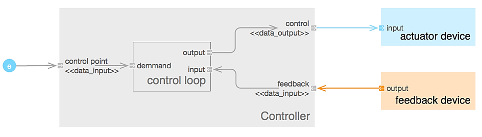
Fig. 7.2 General Scheme of a Control Loop Implementation#
Although the principal function of a Device Control Subsystem is the control of hardware devices, an efficient and robust operation requires the development of other important functions:
Calibration - In many subsystems, calibration software is required to produce error maps or look-up tables (LUT) that allow the control system to perform with the necessary accuracy.
Diagnosis - Some of the GMT hardware subsystems are quite complex. Specific software components are often required to verify the behavior of the system or to troubleshoot it in case of incorrect behavior.
Safety - There are some scenarios where a hardware device could be damaged due to incorrect operation. The Interlock and Safety System (ISS) is ultimately responsible to prevent any damage to equipment or injury to people by the telescope. The ISS “kicks-in” often in a dramatic way. Safety control components provide safe guards to preempt the engagement of the ISS.
Supervision - Often the operation of a subsystem involves coordinating several subordinate components. It is then the TCS responsibility to guarantee that subordinate components are in the correct state and that the performance degrades gracefully in off-nominal scenarios. In addition to managing the configuration, and startup/shutdown of the control subsystems and hardware devices, supervisory components also implement kinematic transformations or anti-collision protection strategies when the system under control requires it.
7.4.1. Controller State Machine#
A state machine represents the operational state of a Component. A set of states addresses the distributed nature of the component and its life cycle management. The Figure below shows the Controller state machine. Only the description of each state is shown. Details about entry actions, transitions and activities are omitted in this diagram.
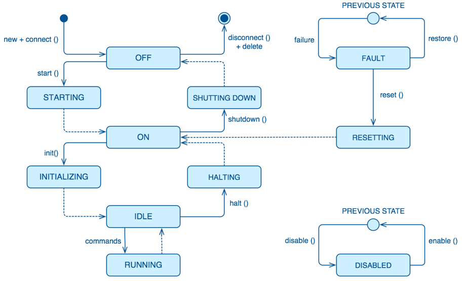
Fig. 7.3 Controller State Machine#
The table below provides the specification of the Controller state machine. The specification defines what actions to implement in every state or transition, however in some of the states each Controller implements its own specific logic.
State |
State Description |
|---|---|
INITIAL |
Initial pseudo state. The Controller is not operational because has not been created yet. The Controller cannot inform this state as it is not running. In this state the software is not running and controlled equipment is not available. |
TERMINAL |
Final pseudo state of any Controller. It’s equivalent to the initial state. A final state cannot have any outgoing transitions. |
PREVIOUS STATE |
This pseudo state is a UML formalism that, within a composite state, allows remembering the previous sub-state that was active prior to leaving the composite state. This is used when a Controller enters the FAULT or DISABLED states. |
OFF |
The Controller is created, loaded and initialized with the default properties, but part of the software and hardware is not initialized and configured yet. All the external Devices controlled by the Controller shall be switched-off. In this state the Controller is not ready for operation, but it is possible to perform tests and diagnostics activities, specially related to the communication capabilities. The Controller is in a static state waiting for events. |
STARTING |
The Controller is being started. Any external equipment controlled by the Controller is being switched on. In some cases, the power supply is shared with other Controllers. It also performs the starting procedure which can include:
|
ON |
The Controller and the connected Devices are already properly initialized and configured. When connected, and depending on the Controller, external equipment shall be in safe state (e.g., brake engaged, motion drives disabled, locking pins inserted). This state can be the final state after a reset or after a power failure. |
INITIALIZING |
While the Controller is in this state the necessary procedures required to make the controller ready to receive operation requests (e.g., find fiducial marks) are executed. |
IDLE |
The Controller is completely idle. It is not serving any command and no data input is driving its control loop. |
RUNNING |
The Controller is serving and operation request. In this state the Controller can receive new commands or is accepting data in its data inputs and sending data through its data outputs. |
SHUTTING DOWN |
Back to OFF state (different for each Controller: power off Devices) |
HALTING |
Back to ON state (different for each Controller: Engage brakes, disable drives) |
FAULT |
The Controller has detected a severe failure and is waiting for an event to occur (e.g., operator input) to correct such situation. |
RESETTING |
Returns to a safe and known state. For example, when the Controller has entered in FAULT state due to the ISS triggering and interlock condition (which can disable drives, remove power, etc.) a reset command must be sent to the Controller. |
DISABLED |
In this state the Controller rejects to perform any control action. This is especially important with Controllers connected to Devices. In this state the Controller does not send demands to the equipment requesting motion or a change (a message is sent to the client indicating that the Controller is disabled). Note that the Controller is ready and it will answer requires asking for some status, but it will not execute any commands that imply acting on the connected Devices. This state can be reached from any state, and when enabled, will return to the previous state. |
Controllers that interface with hardware support specialized operation modes, on-line and simulated:
In on-line mode, controllers try to detect and setup the hardware elements connected to them during startup. If some of the required hardware devices are not available the controller will transition to fault mode. On-line is the default mode when the system is deployed for operation at the observatory.
In simulation mode, controllers will setup the I/O framework in simulation mode. Communication messages with the hardware will be logged, but will not be sent to the hardware devices. Hardware devices will not be powered up during the startup sequence. This mode is intended to be use during development when the hardware is not yet available or is available partially. It also enables controller debugging once the hardware is integrated.
7.4.2. Supervisors#
In addition to direct control of Devices, control subsystems require the implementation of supervisory functions when several Devices have to be operated in a coordinated manner. Supervisors also provide the implementation of the high-level interface to a subsystem. A high- level interface reduces the coupling between subsystems, encapsulates the subsystem implementation details and minimizes the propagation of implementation changes. There could be exceptions due to performance issues (e.g., a component need direct access to the low-latency network). Depending on the specifics of every subsystem, Supervisors can provide the following functions:
Subsystem integrity (e.g., collision avoidance)
Subsystem component configuration (e.g., components are configured in the right sequence and with the right configuration properties, LUTs)
Subsystem robustness (e.g., behavior in presence of no nominal conditions, fault management and tolerance)
Subsystem life-cycle (e.g., startup and shutdown)
Subsystem embedded diagnosis
Subsystem modal transition (for subsystems that have different modes of operation)
Subsystem IO health
7.4.3. Device Controller Library#
Based on the analysis of the degrees of freedom of the telescope (see TCS degrees of freedom), a set of common device control cases have been identified. These cases are based on the motion profiles defined in the IEC 61800-7-201 standard [IEC61800-7-201]. The framework provides a set of Components that implement those cases. The Figure below shows the Controller class hierarchy.
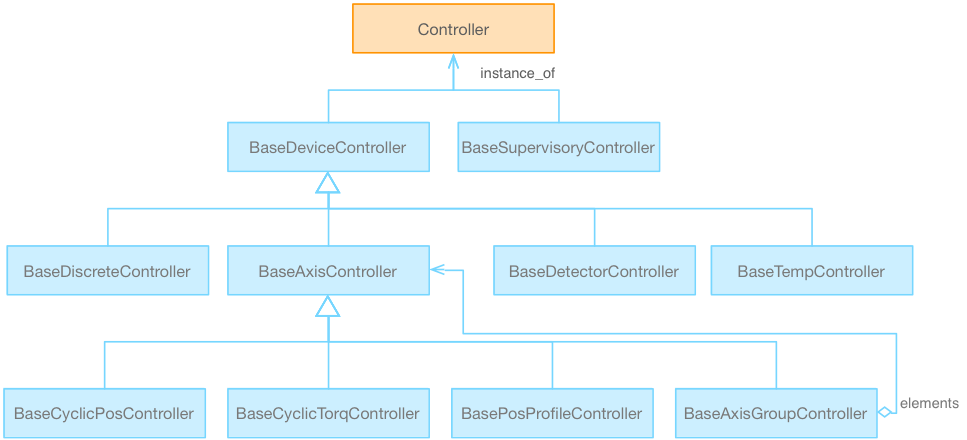
Fig. 7.4 Device Controller Class Hierarchy#
7.4.4. Device Control Subsystem Deployment#
During the design process, the functional description of the Controller features is refined and a hardware deployment model is created as part of the electronic design. The hardware deployment model includes the definition of processing resources and the Input/Output modules that interface with the hardware devices. All this information is captured in the domain model SDFs and used to generate code skeletons and configurations used by the implementation.
The mapping between process image and controller features is completely independent of the protocol used to access the hardware. IOModule adapters provide independence from the specific fieldbus (the Section on I/O Framework describes how the I/O Framework supports this process). The code-block below presents an example of the deployment specification of a Device Control Subsystem:
Host "agws_dcc",
    desc:      "AGWS Control System Device Control Computer"
    location:  "gmt.er_ecab_03"
    buses:
        ecat_01:
            update_rate:  2000
            io_modules:
                E11010:
                    desc:      "Bus Head Coupler"
                    location:  gmt.gir_ecab_01
                    ports:
                        X001:  gmt.dccs.agws_dcc.ether_01
                        X002:  gmt.agws_dcc.ecat.el7301.X001

Subsystem "agws_cs",
    io_routing:
        port:  gmt.agws_dcc.ether_01
        port:  gmt.agws_dcc.ecat.EL1011.X001
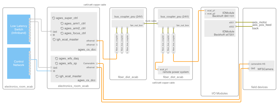
Fig. 7.5 Device Control Subsystem Deployment. Controllers (e.g., agws_arm1_ctrl) are deployed in Device Control Computers (agws_cs_dcc) in the control room electronic cabinets.#