9. HDK example#
9.1. Introduction#
The HDK (Hardware Development Kit) is a tool which has the purpose of serving as a template to facilitate the development of Device Control Systems (DCS).
9.2. HDK Hardware#
The main hardware component of the HDK is the control panel, displayed in Fig. 9.5:
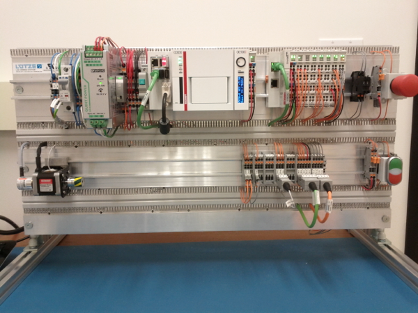
Fig. 9.5 HDK Hardware Control Panel#
The panel has two DIN rails with all the necessary components. The top rail contains the power section on the left, an embedded PC in the central part, and the Ethercat I/O modules on the right (Fig. 9.6), as well as an emergency button (Fig. 9.7). The lower rail contains a stepper motor on the left with a temperature probe (Fig. 9.8), the terminal blocks interface and a couple of push buttons with a led on the right side (Fig. 9.9).
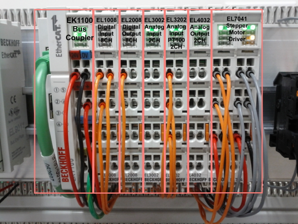
Fig. 9.6 HDK I/O modules#
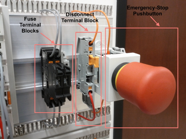
Fig. 9.7 HDK emergency button#
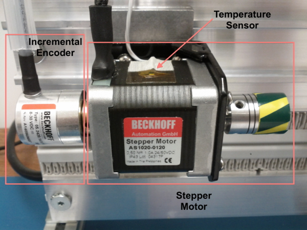
Fig. 9.8 HDK stepper motor#
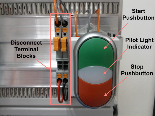
Fig. 9.9 HDK pushbuttons#
For more details on the HDK hardware architecture, refer to GMT document GMT-SWC-DOC-00710.
9.2.1. Connection to the DCC#
The HDK can be controlled using its embedded PC, or using a Real Time Linux DCC. In this example we will use the latter option.
Note
The following instructions assume that the Linux Real Time kernel and the Ethercat drivers have been installed in the DCC, according to the instructions in the Installation Guide document.
The EtherCAT bus must be connected to the RJ-45 connector that is located to the left of the I/O modules block (see Fig. 9.10). The other end of the bus must be connected to the EtherCAT port of the Real Time Linux DCC.
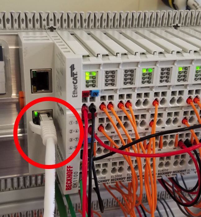
Fig. 9.10 HDK panel EtherCAT bus connection#
We can check that the installation has been done correctly using the
`ethercat` command in the Linux machine. If we execute:
$ ethercat slaves
then the returned output must be:
0  0:0  PREOP  +  EK1100 EtherCAT-Koppler (2A E-Bus)
1  0:1  PREOP  +  EL1008 8K. Dig. Eingang 24V, 3ms
2  0:2  PREOP  +  EL2008 8K. Dig. Ausgang 24V, 0.5A
3  0:3  PREOP  +  EL3002 2K.Ana. Eingang  +/-10V
4  0:4  PREOP  +  EL3202 2K.Ana. Eingang PT100 (RTD)
5  0:5  PREOP  +  EL4032 2K. Ana. Ausgang +/-10V, 12bit
6  0:6  PREOP  +  EL7041 1K. Schrittmotor-Endstufe (50V, 5A)
7  0:7  PREOP  +  EL9508 Netzteilklemme 8V
8  0:8  PREOP  +  EL3356 1K . Ana. Eingang, Widerstandsbr?cke, 16bit, hochgenau
9  0:9  PREOP  +  EL3356-0010 1K . Ana. Eingang, Widerstandsbr?cke, 24bit, hochge
9.3. HDK Software#
9.3.1. Clone the hdk_dcs repository#
On the real-time DCC, clone the repository in the development folder:
$ cd $GMT_LOCAL/modules
$ gds clone hdk_dcs -d gmto
where the -d option defines the git repository owner. The output of the
command will be:
Cloning into 'ocs_hdk_dcs'...
remote: Counting objects: 548, done.
remote: Compressing objects: 100% (44/44), done.
remote: Total 548 (delta 7), reused 19 (delta 1), pack-reused 503
Receiving objects: 100% (548/548), 97.69 KiB | 1.81 MiB/s, done.
Resolving deltas: 100% (247/247), done.
[INF] [gds] clone module hdk_dcs
[INF] [hdk_dcs] Cloning module: hdk_dcs
9.3.2. Model files#
The model files can be found in the $GMT_LOCAL/modules/ocs_hdk_dcs/model/ folder.
- webpack.config.coffee
It has the webpack directives which are needed to build the model
- hdk_dcs_ld.coffee
It is the “loader” file. It contains the
`require`directives to load the rest of the files.- hdk_dcs.coffee
Lists the connectors between the components and the external environment.
- hdk_dcs_def.coffee
High-level definition file, representing the WBS for the submodule. It lists the components, as well as their implementation language, and other properties.
- hdk_dcs_types.coffee
Definitions of structs and data types used by the HDK components.
- hdk_dcs.rst
Text file, in RST format, describing the module.
- hdk_ctrl_pkg/hdk_ctrl_fb.coffee
Fieldbus definitions for the HDK control package.
- hdk_ctrl_pkg/hdk_ctrl_pkg.coffee
Lists the connectors between the components of the hdk_ctrl_pkg package.
- hdk_ctrl_pkg/hdk_main_ctrl.coffee
Definition of the Main HDK Controller component. State variables, input and output ports are specified here. A single instance called hdk_main_ctrl will be created.
- hdk_ctrl_pkg/hdk_hw_adapter.coffee
Definition of the Hardware Adapter component, used to interface with the HDK Actuators and Sensors. State variables, input and output ports are specified here. A single instance called hdk_hw1_adapter will be created.
 hdk_main_ctrl           hdk_hw_adapter         EtherCAT FB
+--------------+      +------------------+      +---------+
|              |      |                  |      |         |
| hmi_inputs   |<-----| operator_buttons |      |         |
| motor_state  |<-----| motor_state      |      |         |
| temperatures |<-----| temperatures     |      |         |
|              |      |                  |<---->|         |
| hmi_outputs  |----->| operator_leds    |      |         |
| motor_ctrl   |----->| motor_ctrl       |      |         |
| sdo_config   |----->| sdo_in           |      |         |
|              |      |                  |      |         |
+--------------+      +------------------+      +---------+
9.3.3. Code generation#
The hdk_dcs repository already has the source code of the HDK, so it is not necessary to generate it.
If the source code needs to be generated again (for example, if some feature to the components must be added), then it can be done using the standard procedure:
$ cd $GMT_LOCAL/modules/ocs_hdk_dcs/model
$ webpack
$ gds gen hdk_dcs
After re-generating code from the model, all manual changes will need to be re-applied.
9.3.4. Compiling Configuration Files#
Configuration files should be compiled for the C++ controllers. This can be done with:
$ gds install  # Copies the configuration file to $GMT_LOCAL/etc/conf/
$ grs compile hdk_dcs
9.3.5. HDK Main Controller Behavior#
The behavior of the HDK is defined in the hdk_main_ctrl component, and more specifically, in the step() function of this controller.
The file that contains the HDK controller step function is `HdkMainCtrl.cpp`.
To visualize or edit it:
$ cd $GMT_LOCAL/modules/ocs_hdk_dcs/src/cpp/
$ cd hdk_ctrl_pkg/hdk_main_ctrl
$ vi HdkMainCtrl.cpp
The contents of the file is:
#include "HdkMainCtrl.h"

using namespace std;
using namespace gmt;

HdkMainCtrl::HdkMainCtrl(
                        const string& comp_uri,
                        const string& comp_name,
                        const string& comp_host,
                        int comp_port,
                        const string& comp_acl,
                        double comp_scan_rate,
                        int comp_prio,
                        int comp_stack_size)
: HdkMainCtrlBase(comp_uri, comp_name, comp_host, comp_port, comp_acl, comp_scan_rate, comp_prio, comp_stack_size)
{
}

HdkMainCtrl::~HdkMainCtrl()
{
}

void HdkMainCtrl::step()
{
    if (!hmi_inputs_val.value.emergency_button)
    {
        motor_ctrl_req.value.velocity = 0;
        motor_ctrl_req.value.enable = false;
    }
    else if (motor_state_val.value.ready && !motor_state_val.value.enabled)
    {
        motor_ctrl_req.value.enable = true; // enable motor if not enabled
    }

    if (motor_state_val.value.enabled)
    {
        if (hmi_inputs_val.value.green_push_button)
            motor_ctrl_req.value.velocity++;
        if (hmi_inputs_val.value.red_push_button)
            motor_ctrl_req.value.velocity--;
        if (!hmi_inputs_val.value.emergency_button)
        {
            motor_ctrl_req.value.velocity = 0;
            motor_ctrl_req.value.enable = false;
        }
    }

    bool moving = motor_state_val.value.moving_positive || motor_state_val.value.moving_negative;
    hmi_outputs_req.value.pilot = moving; // pilot on when moving
    hmi_outputs_req.value.emergency_light = !hmi_inputs_val.value.emergency_button; // ligth on when button pressed
    float estimated_temperature = temperatures_val.value.temp_sensor1 / 10.0;  // 10.0 will be a property

    if (is_step_rate(100))    // every 100 steps = 1 second
    {
        log_info("Green button = " + std::to_string(hmi_inputs_val.value.green_push_button));
        log_info("Red button   = " + std::to_string(hmi_inputs_val.value.red_push_button));
        log_info("Emergency    = " + std::to_string(hmi_inputs_val.value.emergency_button));
        log_info("Temperature  = " + std::to_string(estimated_temperature));
        log_info("Temperature1 = " + std::to_string(temperatures_val.value.temp_sensor1));
        log_info("Temperature2 = " + std::to_string(temperatures_val.value.temp_sensor2));
        log_info("Axis Ready   = " + std::to_string(motor_state_val.value.ready));
        log_info("Axis Enabled = " + std::to_string(motor_state_val.value.enabled));
        log_info("Axis Warning = " + std::to_string(motor_state_val.value.warning));
        log_info("Axis Error   = " + std::to_string(motor_state_val.value.error));
        log_info("Axis Moving+ = " + std::to_string(motor_state_val.value.moving_positive));
        log_info("Axis Moving- = " + std::to_string(motor_state_val.value.moving_negative));
    }

    hmi.value.input = hmi_inputs_val.value;
    hmi.value.output = hmi_outputs_req.value;
    motor.value.state = motor_state_val.value;
    motor.value.command = motor_ctrl_req.value;
    temperatures.value = temperatures_val.value;
}

void HdkMainCtrl::setup()
{
    //setup async input handlers

    //ex: new_async_input_handler ("input_name", this, &HdkMainCtrl::input_handler);

    //add behaviors to features

    //other initializations

}
This step function has 5 parts:
Emergency button
Motor control
LEDs control
Logs
Heartbeat LED
9.3.5.2. Step function. Motor control#
The next section of code implements the motor control:
if (motor_state.enabled)
{
    if (hmi_inputs.green_push_button)
    {
        motor_ctrl.velocity++;
    }

    if (hmi_inputs.red_push_button)
    {
        motor_ctrl.velocity--;
    }

    if (!hmi_inputs.emergency_button)
    {
        motor_ctrl.velocity = 0;
        motor_ctrl.enable = false;
    }
}
In the `green_push_button` field of the `hmi_inputs` input
port we have the state of the green push button of the HDK panel (True
when pushed, False when not) and in the field `red_push_button`
we have the state of the red button (see Fig. 9.9).
The `motor_ctrl` output port has 3 fields: the `velocity` field,
which will be forwarded to the stepper motor as the velocity set point; the
`enable`, which will control if the motor is enabled or not; and the
`reset`, which resets the motor in case of failure.
The logic of the section is straightforward: if the green button is pushed, the velocity will be increased; if the red button is pushed the velocity will be decreased; and if the emergency button is pushed then the motor is disabled.
9.3.5.3. Step function. LEDs control#
The next code section takes care of the control of the LEDs:
bool moving = motor_state.moving_positive || motor_state.moving_negative;
hmi_outputs.pilot = moving; // pilot on when moving
hmi_outputs.emergency_light = !hmi_inputs.emergency_button; // ligth on when button pressed
In the fist line we read the motion state of the stepper motor, and in the second line we light the white led (see Fig. 9.9) if the motor is moving. In the third line, we light the red led (Fig. 9.7) if the emergency button is pushed.
9.3.5.4. Step function. Logs#
Once each second, the HDK application produces some logs to inform about the slaves readings:
if (is_step_rate(100))    // every 100 steps = 1 second
{
    // following values should go to user interface
    log_info("Green button = " + std::to_string(hmi_inputs.green_push_button));
    log_info("Red button   = " + std::to_string(hmi_inputs.red_push_button));
    log_info("Emergency    = " + std::to_string(hmi_inputs.emergency_button));
    log_info("Temperature  = " + std::to_string(estimated_temperature));
    log_info("Temperature1 = " + std::to_string(temperatures.temp_sensor1));
    log_info("Temperature2 = " + std::to_string(temperatures.temp_sensor2));
    log_info("Axis Ready   = " + std::to_string(motor_state.ready));
    log_info("Axis Enabled = " + std::to_string(motor_state.enabled));
    log_info("Axis Warning = " + std::to_string(motor_state.warning));
    log_info("Axis Error   = " + std::to_string(motor_state.error));
    log_info("Axis Moving+ = " + std::to_string(motor_state.moving_positive));
    log_info("Axis Moving- = " + std::to_string(motor_state.moving_negative));
}
The `is_step_rate(num)` function returns true once each `num` steps, so the
above code gets executed once each 100 steps. As the HDK scan rate is 100 Hz,
this section is entered once each second.
Inside the if statement we have several `log_info` to show the different
variables. The `log_info` method is inherited from the BaseComponent base
class, and it sends the given string to the Log Service.
9.3.5.5. Step function. Heartbeat LED#
Finally, the section
if(is_step_rate(500))  // every 500 steps = 5 seconds
{
    // flip bit to indicate component is alive
    hmi_outputs.heartbeat = !hmi_outputs.heartbeat;
}
inverts the state of the heartbeat LED, with a period of 5 seconds. This digital output is not actually wired to any hardware device, but the change is visible in the LED array of the digital output EL2008 Ethercat slave.
9.3.6. Compilation#
To compile the C++ Control Package code of the HDK, edit the module.mk file to contain the correct library definitions:
$ vi $GMT_LOCAL/modules/ocs_hdk_dcs/src/cpp/hdk_ctrl_pkg/module.mk
Ensure that the following lines are defined:
# Add in this file the compile flags for the package, eg:
MOD_BUILD_LDFLAGS += -lcore_core_pkg -lio_core_pkg -lctrl_core_pkg -lio_ethercat_pkg
MOD_BUILD_LDFLAGS += -lethercat
Run make to compile the code:
$ cd $GMT_LOCAL/modules/ocs_hdk_dcs/src/cpp
$ make
9.3.7. Running the Example#
Start the logging and telemetry services:
$ log_server &
$ tele_server &
Start the HDK application in the background
$ hdk_ctrl_app &
The application is running in the background and will not provide any console output. All output will be directed to the logging service after the components have been successfully set up.
9.3.7.1. Log client#
In a separate terminal (for example, tty2), start the logging service client.
$ log_client listen
9.3.7.2. Telemetry client#
In a separate terminal (for example tty3), start the telemetry service client.
$ tele_client listen
9.3.7.3. HDK operation#
Now the HDK is available to be operated. The behaviour of the system will be the described one:
If the emergency button is pressed, then the stepper motor will be disabled, and the red led of the emergency button will be on.
If the emergency button is released, then the stepper motor will be enabled, and the red led of the emergency button will be off.
When the emergency button is released, if the green button is pushed then the velocity of the stepper motor will be increased.
When the emergency button is released, if the red button is pushed then the velocity of the stepper motor will be decreased.
If the motor is moving, then the pilot led between the buttons will be on.
9.4. User Interface#
The Navigator application displays the Engineering user interface as well as any custom panels defined in the subsystem’s Visualization Package.

The above image shows the HDK DCS’ UI contained in the visualization package. This is a basic example of what’s possible to do in a visualization package. More detailed examples will be added in the future as the UI Framework matures.
9.4.1. Configuration#
The Navigator app uses your bundles and configuration to connect to your DCS components. If your component instance is running on a different machine, you will need to update your configuration files in $GMT_LOCAL/etc/conf to point to the IP address of the target computer. You can quickly udpate all your config IPs like so:
$ cd $GMT_LOCAL/etc/conf/hdk_ctrl_pkg/hdk_main_ctrl/
$ sed -i '' "s/172.0.0.1/172.16.10.31/g" hdk_main_ctrl_config.coffee