3.8. Modules: Subsystem, Packages, Components#
The SWCS domains (TCS, OPS, OSRV) are each composed of software subsystem modules. As illustrated in the bottom row of the SWCS Organization figure, each subsystem is then made up of components organized into packages according to their affinity or relationships. The SWC reference architecture [Filg13b] defines a guide for organizing subsystem components into a set of canonical packages. Examples of packages and their components are shown in Tables below on Control Packages and Core Components. Which packages exist in which subsystem depends on the specific functionality (e.g., some subsystems do not require special calibration components, or do not interface with hardware devices). The tables below describe this pattern, split in two categories:
Control Packages – These packages are included in subsystems that involve the control of optomechanical hardware Devices.
Operation Support Packages – These Packages include software components necessary to support health monitoring, automation, and proper operation of a Subsystem. Diagnosis and calibration packages are emphasized early on in the design. This is an area that is often overlooked despite the fact that they may take a significant amount of development effort, especially in the case of complex adaptive optics control subsystems.
CONTROL PACKAGES |
||
|---|---|---|
Package Name |
Description |
Typical Components |
Device Control Package |
Contains software Components that implement the supervisory and control functions of a Device Control Subsystem (e.g. Mount Control System Control Package). |
Supervisor, Controller |
Data Acquisition Package |
Contains software Components that implement the supervisory and data acquisition functions of a Detector Control Subsystem (e.g., AGWS Slope Processor Package). Only Subsystems that include a Wavefront Sensor (WFS), acquisition/guide camera or a science detector need to provide a Data Acquisition Package. |
Supervisor, Controller, Pipeline, |
Hardware Package |
Contains hardware Components in which to deploy the Device Control or Data Acquisition Package software Components and the hardware to interface with the electromechanical Devices. |
Device Control Computer, I/O Module |
OPERATION SUPPORT PACKAGES |
||
|---|---|---|
Package Name |
Description |
Typical Components |
Sequencing Package |
Contains sequence Components necessary for the operation of the Subsystem |
Sequence |
Diagnosis Package |
Contains software Components necessary to implement diagnosis functions when required. This may involve the development of special control or operation modes. |
Supervisor, Controller, Pipeline, Sequence |
Calibration Package |
Contains software Components necessary for the calibration and characterization of hardware Devices. This may include the development of special control or operation modes. |
Supervisor, Controller, Pipeline, Sequence |
Data Processing Package |
Contains software Components necessary for the calibration and processing of science and wavefront sensor detectors. |
Supervisor, Pipeline, |
Visualization Package |
Contains software Components that provide custom visualizations necessary for the efficient operation of a given Subsystem (e.g. M1 global status Panel). Note that default engineering Panels are available as part of the Engineering UI service. |
Panel, Widget |
Safety Package |
Contains hardware/software Components that implement Subsystem specific safety functions. These Components often interface with the ISS but are independent (e.g. M1 safety controller). |
Supervisor, Controller, |
Operation Workflows Package |
Contains Components that allow the automation of high-level operation workflows relative to the subsystems (e.g. unit test workflow, or calibration workflow in case that several sequences and human operations are involved). |
Workflow |
Management Package |
Contains Components that capture the development backlog and the Assembly Integration and Testing plans. |
Plan, Workflow |
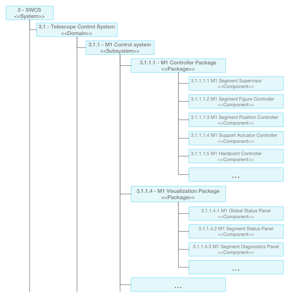
Fig. 3.8 M1 Control System Package and Components Excerpt#
The Figure above shows an example of the component organization for the M1 Control System. The structure of all the SWCS Subsystems has been analyzed and developed following this pattern. As described above and later, Domain Engineering helps to identify sets of common components that are the elementary building blocks of the SWCS subsystems. The figure on Core Components below shows those core component classes. Each component is defined by a set of Component Features whose definitions are detailed in Core Framework. In fact, all SWCS modules, including subsystems, packages, and components are fully specified by a text file containing their features, as shown in the example of BaseLinearAxisController. The Section on Subsystem Specification and Modeling explains the formal specification process in more detail.
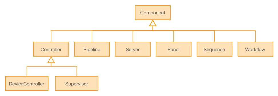
Fig. 3.9 Core Components#
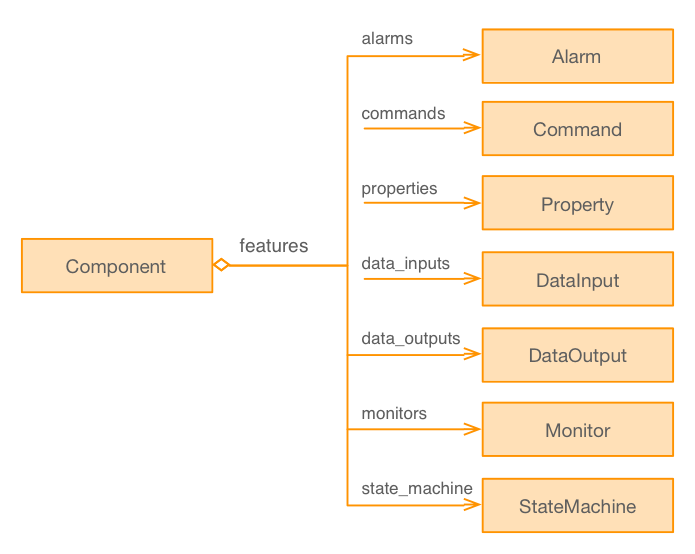
Fig. 3.10 Component Features#
Each Component has been assigned to a class that defines its default behavior in the corresponding specification file. The following code-block excerpt shows an example of the specification file that defines the interface and features of a BaseLinearAxisController (Device Control Framework provides an overview of common motion control Components). This specification is based on the IEC 61800-7-201 [IEC61800-7-201] Standard. The standard is concrete, but at the same time is designed to cover a majority of the motion control use cases. The design process captures when a Component (e.g., agws_radial_stage_ctrl) fits this default behavior. This approach provides several benefits:
The specification of the component captures performance data, interfaces, etc., all of which are used directly in the final implementation. Furthermore, the specification closely dovetails a well-developed and industrial standard, which significantly reduces the effort needed to capture all the information. This is in sync with the way industrial companies specify their subsystems. This often allows one to implement the controller in a standard off-the-shelf smart drive, relieving the computing platform of the responsibility to perform all the real-time functionality. As the control loops run in dedicated standardized controllers, it is then feasible to implement a layer that integrates the controller with the rest of the observatory services using more productive high-level languages (Software Development Platform).
The mapping between specification and implementation is as direct as it gets, and greatly facilitates the traceability of requirements.
The interfaces of similar Components share the same detailed specification (e.g., the interfaces of all the linear stages are the same). This not only allows the development of common control Components, but the possibility to reuse common visualization or calibration Components, as well as testing procedures.
It is possible to specify accordingly the majority of the elementary degrees of freedom of the GMT as well as some Axis Groups (e.g., BaseLinearXYController for a Cartesian linear stage), as discussed in Telescope Control System. It is also possible to incorporate fault management, and startup/shut down procedures in the same manner modeled using supervisor components. Supervisors are usually more specific to the application and their implementation, thus require more customization. Other domains, like user interface components or data processing components have been subject to the same design process. User Interface Framework and Data Processing Framework sections describe them respectively.
properties:
    max_torque:
        desc:     "This property shall indicate the configured maximum permissible
                   torque in the motor. The value shall be given per thousand of rated
                   torque."
        type:     "uint16"
        pattern:  "pull"
        max_rate: 1
        default:  1000

    motor_rated_torque:
        desc:     "This property shall indicate the configured motor rated torque.
                   It is taken from the motors nameplate. All relative torque
                   data shall refer to this value. For linear motors, the object
                   name is not changed, but the motor rated force value shall be
                   entered as multiples of mN (milliNewton). The value shall be
                   given in mNm (milli Newton metre)."
        type:     "uint32"
        pattern:  "pull"
        max_rate: 1
        default:  1000

    motion_profile_type:
        desc:     "This property shall indicate the configured type of motion profile
                   used to perform a profiled motion.

                     Value        | Definition
                     -------------|----------------------------------
                     -32768 to -1 | Manufacturer-specific
                     0            | Linear ramp (trapezoidal profile)
                     1            | Sin2 ramp
                     2            | Jerk-free ramp
                     3            | Jerk-limited ramp
                     4 to 32767   | Reserved"
        type:     "int16"
        pattern:  "pull"
        max_rate: 1
        default:  0
BaseLinearAxisController Specification File excerpt