8.1. Computing Platform#
Device Control Subsystems are deployed in standardized GMT Device Control Computers (DCCs), while general processing components are deployed in Data Processing Computers (DPCs).
Two types of DCCs are supported: Intel Industrial Computers (PCs) running Linux and Programmable Logic Controllers (PLCs). In addition to the obvious benefits of maintainability and cost-effectiveness, the use of standardized computer architecture ensures that software components can adequately and robustly compile and deploy on them.
PC based DCCs running Linux with real time extensions are used in the following use cases:
The Device Control Subsystem has to be integrated with the low latency network.
High computing performance is required.
Complex operation scenarios.
PLCs are used in the following use cases:
The bandwidth necessary for telemetry is low.
Simple supervision, coordination or operation scenarios.
8.1.1. Computer Hardware#
The current baseline consists of standard off-the-shelf data center class computers. The Table below presents the characteristics of the computer platform. The interface with field devices is done using EtherCAT, a real-time Ethernet based fieldbus, which only requires the availability of standard network ports. This is in contrast with backplane-based systems (e.g., VME, PXI) where the field interface is implemented with cards connected to the backplane. The Section on Field Device Interface Technology describes with more detail the characteristics of EtherCAT. The fact that modern motor drivers include embedded motion controllers and even some local logic by means of a PLC reduces the performance requirements on the computing platform. As a consequence computers can be very compact. Data center class computers are used to improve system reliability (e.g., redundant power supplies). This configuration has been used during prototyping activities. The physical and power consumption envelope of these computers will be optimized once the project approaches its deployment phase.
Some of the computer components are optional as their use depends on the functions performed by the software components deployed in them. For example, DCCs require access to the fieldbus, but many of them do not require access to the low latency network. DPCs do not require access to the fieldbus, but require high capacity storage for quick processing of intermediate results.
The table below shows the GMT Base Computer Specification:
Category |
Description |
Function |
|---|---|---|
Processor architecture |
Mulcore Intel CPU |
Data processing and control processes execution. Hardware acceleration |
Storage |
SATA/PCIe solid state disk |
OS image, local telemetry circular buffer |
Memory |
> 4 GB RAM |
Process memory, ultra-fast telemetry circular buffer |
Networking |
2 x 1 GbE |
EtherCAT fieldbus network interface with cable redundancy. |
2 x 10 GbE |
Observatory Service network interface |
|
1 x 40 Gbps Infiniband |
Low latency network interface |
|
Hardware acceleration |
PCIe GPU |
Hardware acceleration of wavefront processing and reconstruction |
The figure below provides the description of the two control subsystem deployment architectures. The choice between one over the other is part of the TCS architecture design process and will be analyzed in a case-by-case basis during detailed design. Examples of the Single Tier Control configuration are the Mount Control System or the M1 Control System. The Enclosure Control System follows the Two Tier Control design as it fits the capabilities of the industrial companies that may procure the low-level control system integrated with the rest of the enclosure.
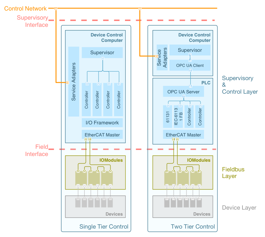
Fig. 8.1 Single and Two tier Controller Architecture#
8.1.2. PLCs#
Programmable Logic Controllers (PLCs, PACs and Soft PLCs) are used in several specific areas, as in the case of the Enclosure for rotating the dome and commanding shutters and wind vents. PLCs are required to use the IEC 61131-3 [IEC61131-3] programming standard widely adopted in industry. This part of IEC 61131 specifies the syntax and semantics of a unified suite of programming languages for programmable controllers. These consist of two textual languages: Instruction List and Structured Text, and two graphical languages: Ladder Diagram and Function Block Diagram. Also, Sequential Function Chart elements are defined for structuring the internal organization of programmable controller programs and function blocks [IEC61131-3].
Programmable controllers are integrated with the rest of the Observatory using the OPC Unified Architecture (OPC UA) communications standard [Soto13]. OPC UA is the next generation OPC standard that provides a cohesive, secure and reliable cross platform framework for access to real time and historical data and events.
PLCopen provides another important programming solution to the wide range of selectable motion control hardware available. PLCopen motion standard provides a way to have standard application libraries that are reusable for multiple hardware platforms. This lowers development, maintenance, and support costs while eliminating confusion. Standardization comes about by defining libraries of reusable components so that the programming is less hardware dependent, increasing the reusability of the application software, and enabling the application to scale across different control solutions (see plcopen.org).
Currently the suite of PLCopen Motion Control Specifications consists of 6 parts, of which GMT will adopt Part 1: Function Blocks for Motion Control.
A Soft PLC is a control software engine that runs on standard CPUs such as Intel, ARM, PowerPC, etc. Combining the features of a PLC (such as I/O control, PID, ladder logic, standard industrial communication protocols) with the power of computers (e.g., data handling, logging, running multiple applications simultaneously, communications over standard networks, user functions, database interfaces) a Soft PLC provides the most comprehensive industrial control solution on the market. The GMT’s preferred choice for soft PLC is the TwinCAT PLC automation software. TwinCAT PLC engine runs on a standard PC/IPC hardware. It has a real-time kernel with a cycle time typically on the order of microseconds, with a choice of fieldbus including EtherCAT. TwinCAT PLC offers all the languages in the IEC 61131-3 standard and has a powerful development environment for programs whose code size and data regions far exceed the capacities of conventional PLC systems.
8.1.3. Operating Systems#
Low-latency, deterministic, system performance is required for real-time control and signal processing applications that must respond to external events in a predictable manner, independently of other considerations and particularly the workload. Furthermore, low jitter operation of the fieldbus master is required for some elaborate control loops (e.g., multi-axis interpolation) and for high rate, low jitter, telemetry sampling. For those reasons, digital or motion control applications are often built on top of a real-time operating system that specially addresses:
concurrent, multi-tasking applications
task scheduling and priority policies
deterministic, low latency responses
interfaces to hardware
Several benchmarks [Bec12b] and tests have been performed in order to assess the adequacy of several Linux real-time extensions. The Linux kernel / GNU-Linux operating system has a long track record of reliability for server and embedded systems, and excellent soft real-time performance. RT_PREEMPT is very flexible and actively developed, and has the performance needed for all control systems requirements considered so far.
A typical control loop requires periodic execution at a predefined rate. Linux offers different kinds of timers, depending on hardware availability. The High Resolution Timers introduced in kernel 2.6 provide nanosecond resolution. The next two Figures show the results of some of the tests performed. The tests include also the performance of the EtherCAT master stack.
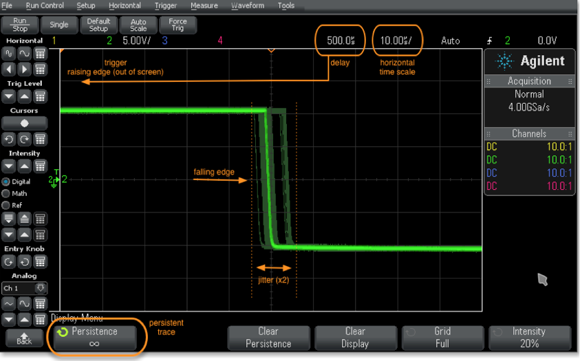
Fig. 8.2 High Resolution Timer Benchmark @ 2KHz#
The above Figure shows a high resolution timer benchmark at 2KHz. In this benchmark, a callback is scheduled to run every 500 microseconds, generating a square waveform using a digital output channel on the host. The waveform is captured on an oscilloscope where timing accuracy and jitter are measured.
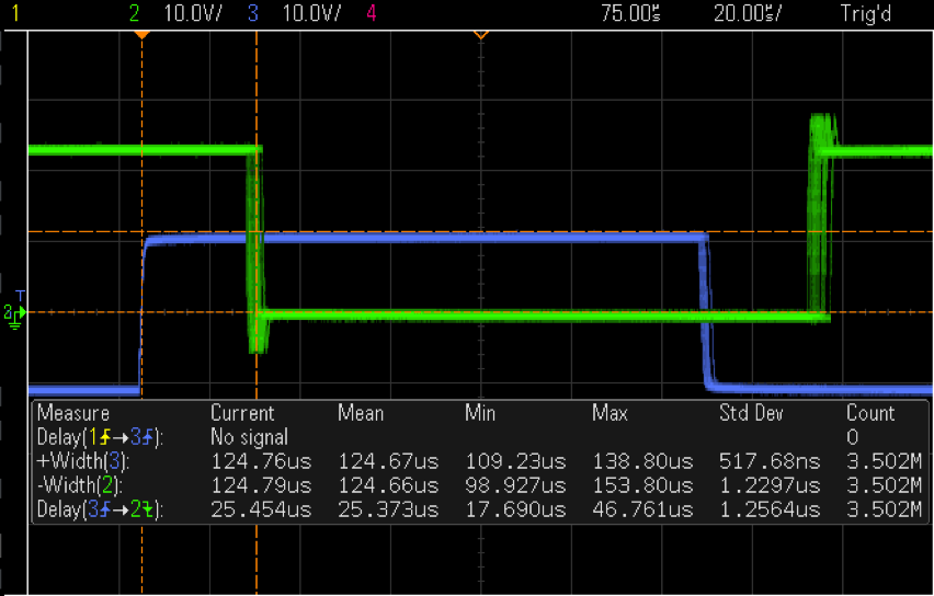
Fig. 8.3 High Resolution Timer Benchmark with 3.5 Million Samples @ 8 kHz#
The above Figure shows a high-resolution timer benchmark now at 8 kHz. A callback is scheduled to run every 125 microsecond. The blue curve shows the waveform. The oscilloscope triggers on the rising edge; the green curve can be ignored as EtherCAT response was being tested in parallel. Over 3.5 million samples collected, the signal shows a (static) clock skew of 330 nanoseconds (125.00 - 124.670), maximum jitter of 29 microseconds with 517 nanoseconds rms.