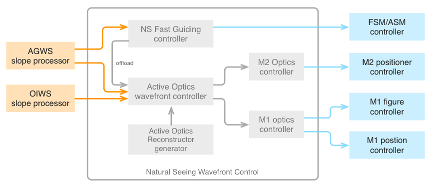
The simplest observing mode is natural seeing. A simplified control block
diagram of the Natural Seeing (NS) WFC is shown in the Figure below. Software
components associated with sensors are shown in orange, WFC components in grey,
and those associated with optical compensators in blue. Arrows indicate data
flow, color-coded by the type of data: Orange for WFC inputs, gray for internal
data flow between WFC components, and blue for WFC outputs. The WFC includes two
types of controllers: Wavefront controllers, which convert sensor measurements
to residual wavefront, and optics controllers which convert those wavefronts to
mechanical degrees of freedom.
Fig. 5.9 Natural Seeing wavefront control system simplified block diagram#
The NS wavefront control functionality is split between two controllers: The NS
Fast Guiding controller and the Active Optics Wavefront Controller. The Active
Optics Wavefront Controller is common to all observing modes, though its
reconstructor matrix changes. It provides updates to the mount pointing, M1 and
M2 segment positioning, and M1 segment figure based on the wavefront slopes sent
by the AGWS Slope Processor, and optionally an On-Instrument Wavefront Sensor
(OIWFS, typically measuring tip-tilt or tip-tilt-focus). The NS Fast Guiding
Controller converts AGWS guider signal to fast tip-tilt commands for either the
FSM or ASM, and offloads the average FSM/ASM tilt to telescope pointing (not
shown).
Overview
Four main control loops operate simultaneously in the natural seeing mode:
The Slow Guiding control loop updates the pointing kernel guiding offsets
based on low- pass filtered AGWS average wavefront tilt measurements.
The Fast Guiding control loop updates the tip-tilt of the FSM (or ASM)
based on full-rate AGWS segment tilt measurements.
The Active Optics control loop updates the positions of the M1 and M2
segments, and the figure of M1, based on AGWS wavefront sensor
measurements.
The Flexure control loop updates the position of the AGWS probes based on
On- Instrument Wavefront Sensor measurements.
The natural seeing mode fast and slow guiding control loops, and their
expected performances, are described in detail in Section 6.12.3 [John13].
The Active Optics control loop and its performance are detailed in Section
6.12.2 [John13]. In addition to these main feedback loops, there is also an
offload between the fast guiding controller and the pointing kernel to avoid
saturation of the FSM or ASM tip-tilt actuators.
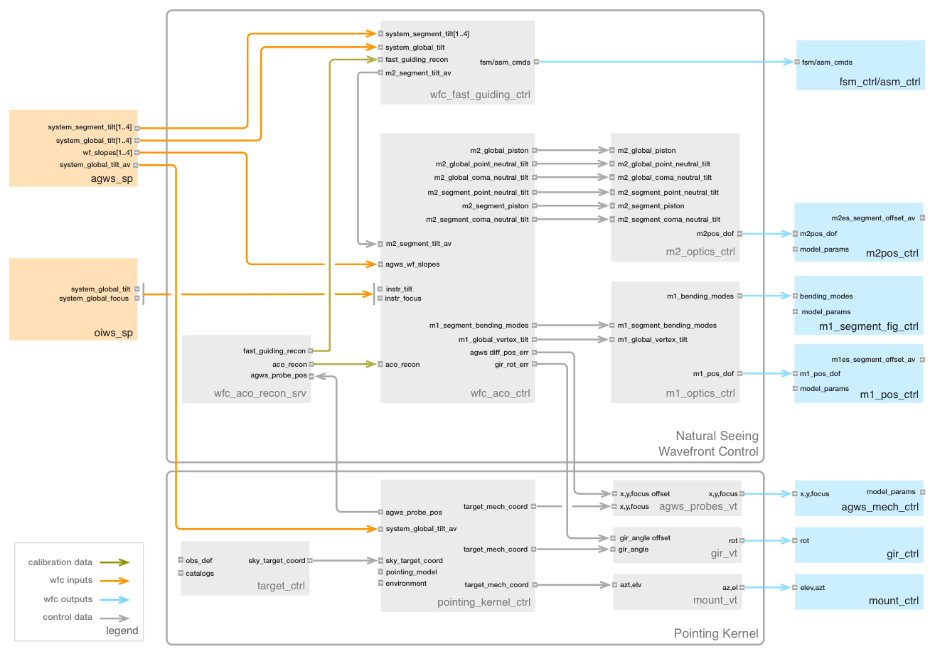
Component Descriptions
The Figure below shows a detailed block diagram of the natural seeing WFC,
including all of the real-time software components currently envisioned.
External components with interfaces to the WFC (e.g., sensor slope
processors and mirror controllers) are also represented. Ports are
identified with the input of output data type, and data flow with arrows.
Telemetry is not explicitly shown, as it is provided as a system service to
every component.
A list of natural seeing WFC components is provided in Table 10-17. A
description of the most critical components is given below, followed by an
identification of the connections between them. Note that wavefront
aberrations have been identified using the following nomenclature:
Global aberrations are defined over the full GMT pupil, while segment
aberrations are defined over each segment.
System aberrations represent a measurement of the full telescope
optical system, while M1, ASM, etc., aberrations represent only the
contribution of one optical surface.
Temporal averages of an aberration are identified as aberration_av.
Table 5.12 Natural Seeing Wavefront Control System Components#
Component Name
Description
Software Package
wfc_fast_guide_ctrl
Fast Guiding Controller
wfc_ns_pkg
wfc_aco_ctrl
Active Optics Controller
wfc_common_pkg
wfc_aco_recon_srv
Active Optics Reconstructor Server
wfc_common_pkg
m1_optics_ctrl
M1 Optics Controller
wfc_common_pkg
m2_optics_ctrl
M2 Optics Controller
wfc_common_pkg
At the present time, all aberrations except the M1 bending modes are defined
using Zernike polynomials [Noll76].
AGWS Slope Processor
While the AGWS slope processor is not a component of the WFC, it is
presented here for completeness. The AGWS slope processor converts the AGWS
camera images into wavefront slopes, by computing the centroid of star or
Shack-Hartmann spot images relative to reference pixel positions. The
component’s input and output ports are listed in the Table below.
There are four cameras in the AGWS. Each camera may be operated in one of
four modes: Idle, Guide, TT7 and SH-WFS. The number of positions in the
reference list will vary from 1 in Guide mode to 7 in TT7 mode, and ~576 in
SH-WFS mode. New images may be available as rapidly as 206 Hz in WFS mode,
402 Hz in TT7 mode, and up to 2 kHz in Guide mode. The operating mode of the
camera will control the output port to which its wavefront slopes are
provided.
List of [x,y] expected positions of each WFS
subaperture or guider image.
pixel
18.4
1
Input
agws wf
offset
List of [x,y] offsets from the reference
positions of each WFS subaperture or guider
image.
mas
18.4
1
Input
system global
tilt
Difference between agws_wf_ref and computed
centroid position for cameras in Guide mode,
or average of the slopes for cameras in TT7
mode, in the probe coordinate system.
mas
0.032
2000
Output
system segment
tilt
Difference between agws_wf_ref and computed
centroid position for cameras in TT7 mode,
in the probe coordinate system.
mas
0.224
402
Output
agws wf slopes
Difference between agws_wf_ref and computed
centroid position for camera in WFS mode,
in the probe coordinate system.
mas
18.4
206
Output
system global
tilt av
Low-pass filtered system global tilt. If no
probe in Guide mode, derived from probe in
TT7 mode.
mas
0.008
20
Output
agws sp flag
Quality flag for each slope measurement.
boolean
9.2
206
Output
agws sp fwhm
FWHM of each subaperture image.
mas
18.4
206
Output
agws sp snr
SNR of each slope measurement.
N/A
18.4
206
Output
agws sp flux
Integrated flux in each subaperture.
count
18.4
206
Output
agws sp bkg
flux
Measured background flux in each subaperture.
count
18.4
206
Output
agws sp cent
Raw computed centroid in each subaperture.
pixel
18.4
206
Output
Reference positions are provided by the Active Optics Reconstructor
Server and may be modified by offsets provided by other components in the
control system. For example, the AGWS Supervisor component might provide
open loop calibration offsets dependent on the camera probe location and
gravity vector, and the telescope control system might provide guide or
other offsets to affect coordinated dithers or other tracking functions.
In addition to full-rate centroid data, the AGWS slope processor will
compute a low-pass filtered average wavefront tilt (from Guide, TT7, or
WFS mode measurements) and provide this to the pointing kernel for slow
guiding of the mount. Other parameters such as SNR, FWHM, and flux per
subaperture will be computed for each camera and sent to the telemetry
system. These values will be used by the Active Optics Reconstructor
Server to correctly weight the measurements and verify pupil mapping.
Fast Guiding Controller
The Fast Guiding Controller computes the segment tip-tilt commands that
will be sent to either the FSM or ASM controller, depending on the M2
assembly installed. Its data interfaces are listed in the following Table:
Global tilt error in the probe coordinate system.
Used only if system_segment_tilt is not available.
mas
0.032
2000
Input
system segment
tilt
Segment tilt error in the AGWS probe coordinate
system.
mas
0.224
402
Input
fast guide
recon
Fast guiding reconstructor matrix. Converts Guide
or TT7 centroids to system segment tilt in
telescope coordinate system.
n/a
3.1
0.3
Input
m2 segment
tilt
Absolute segment tilt commands to each FSM
segment, in the telescope coordinate system.
mas
0.056
2000
Output
m2 segment
tilt av
Time-average segment tilt, to offload to the M2
Positioner.
mas
0.056
0.3
Output
In routine operation, the Fast Guiding Controller will close the servo
control loop between the system segment tilt error measured by one AGWS
probe in TT7 mode, and the absolute FSM or ASM segment tilt and piston
commands. If no probe is configured in the TT7 mode, then global tilt
measured by a probe in guide mode will be used. The Fast Guiding Controller
must rotate the measured tilt error into the telescope coordinate system,
and appropriately average measurements of multiple probes if several happen
to be in TT7 or guide mode. This is done with a single matrix
multiplication. Note that the low-pass filtered system global tilt error is
simultaneously sent from the AGWS slope processor to the pointing kernel,
and corrected at low bandwidth (~2 Hz) by the mount.
The time average of the M2 segment tilt is also computed, and offloaded to
M2 Positioner via the Active Optics Controller to avoid saturation of the
FSM/ASM tilt actuators.
Active Optics Wavefront Controller
The Active Optics Wavefront Controller maintains the alignment of the
telescope and the figure of M1 and M2. The controller multiplies the vector
of wavefront slopes measured by the three AGWS probes in WFS mode by a
reconstructor matrix to compute the necessary corrections. The AGWS cameras
in WFS mode will be synchronized, and will typically use 30 s integrations
to average out atmospheric turbulence. The 319 error terms output by the
matrix multiplication are summarized in Table 10-20. These are sent to the
M1 and M2 optics controllers, as shown in Figure 10-22. The optics
controllers enforce the stroke and force limits, and may therefore convert
low-order bending modes into segment rigid body motion as required.
Table 5.15 Active Optics Reconstructor Output Terms#
Output Terms
Degrees of
Freedom
Controlled Aberrations
M1 global vertex tilt
2
Global field-dependent focus
M2 global pointing-neutral tilt
2
Global coma
M2 global coma-neutral tilt
2
Global field-dependent astigmatism
M2 segment pointing-neutral tilt
2×6
System segment coma
M2 global Z position
1
System global focus
M2 segment Z position
6
System segment focus
M1 bending modes 5,6,9-45
38×7
M1 segment figure
M2 segment Zernike modes 5,6,9,10
4×7
M2 low-order segment figure (ASM only)
GIR rotation error and differential probe position errors are determined by
computing the average tip and tilt measured by each AGWS camera in WFS mode,
and fitting these with a geometrical model. Any average rotation around the
camera in Guide or TT7 mode is interpreted as a GIR rotation error, while
the residual tip-tilt errors after the rotation is subtracted are
interpreted as differential position errors of the WFS probes. GIR rotation
error and differential probe position error are sent to the pointing kernel.
A complete list of the Active Optics Wavefront Controller data interfaces is
given in Table Table 5.16. This component is common to all
observing modes, but the reconstructor is different for each mode. The
observing modes for which the ports are active are indicated in the last
column.
Active Optics Reconstructor Server
The Active Optics Reconstructor Server generates the reconstructor matrices
for fast guiding and active optics correction. Each of these depends on the
observing mode, the configuration of the AGWS probes, their positions in the
DG focal plane, and the angle of the GIR. The component’s data interfaces
are listed in Table 5.17.
The reconstructor matrix for fast guiding simply average and rotate
wavefront slope vectors and can be computed analytically. The active optics
reconstructor matrix is more complex, and the strategy followed to date (see
Section 6.12.2.5 [John13]) is to raytrace the spots of each Shack-Hartmann
camera using Zemax. An unperturbed model of the telescope and AGWS wavefront
sensors is first traced to provide reference spot positions. The model is
then perturbed in each of the 319 degrees of freedom listed in
Table 5.15, and the difference
between the centroids and their reference positions provides a column in the
system matrix. Finally, the reconstructor is computed by taking the
pseudo-inverse of this system matrix.
The reconstructor is dependent on each sensor’s position and orientation in
the telescope focal plane. Simulations have shown that when tracking near
zenith, the matrix must be updated every ~15 seconds to avoid significant
reduction in the delivered image quality due to the rapid rotation of the
GIR [McLe13]. Active optics updates may have to be interrupted during a
transit near zenith when the pupil rotation rate exceeds 6 deg/min.
Table 5.16 Active Optics Wavefront Controller Ports#
Port Name
Description
Unit
Size
(kB)
Rate
(Hz)
Type
Mode
agws wf
slopes
S-H centroids from up to 4 probes,
in frame of of reference of sensors,
potentially updated asynchronously.
mas
18.4
206
Input
All
oiws system
global tilt
System global tip-tilt error measured by
an OIWFS, in instrument coordinate system.
mas
0.008
1
Input
NS &
GL
oiws system
global focus
System global focus error measured by an
OIWFS, in instrument coordinate system.
Reconstruction matrix, computed based on
AGWS probe position, observing mode, and
GIR angle.
n/a
2925
0.3
Input
All
m2 global
piston
Global Z position command to M2
Positioner, from AGWS or ASM system
global focus.
μm
0.004
0.3
Output
All
m2 global
point neutral
tilt
Global pointing-neutral tilt command to
M2 Positioner, from AGWS or ASM system
global coma.
μrad
0.008
0.3
Output
All
m2 global coma
neutral tilt
Global coma-neutral tilt command to M2
Positioner, from AGWS system field-
dependent astigmatism.
μrad
0.008
0.3
Output
All
m2 segment
point neutral
tilt
Segment pointing-neutral tilt command to
M2 Positioner, from AGWS system segment
coma.
μrad
0.048
0.3
Output
NS
m2 segment
piston
Segment Z position command to M2
Positioner, from AGWS system segment
focus.
μm
0.048
0.3
Output
NS
m1 global
vertex tilt
Global tilt command to M1 Positioner,
from AGWS system field-dependent focus.
μrad
0.008
0.3
Output
All
m1 segment
bending modes
M1 segment bending modes 5,6, 9-45.
μm
RMS
1.04
0.3
Output
All
m2 segment
lo modes
ASM segment Zernike modes 5,6,9,10.
μm
RMS
0.11
0.3
Output
NS
agws diff
pos err
AGWS probe position error, from AGWS
global tip-tilt.
μm
0.032
0.3
Output
All
gir rot err
GIR rotation error, from AGWS global
tip-tilt.
μrad
0.004
0.3
Output
All
Table 5.17 Active Optics Reconstructor Server Ports#
Port Name
Description
Unit
Size
(kB)
Rate
(Hz)
Type
agws probe posn
AGWS probe position, in telescope
coordinate system.
mm
0.032
1
Input
gir posn
GIR position, in telescope coordinate system.
deg
0.004
1
Input
fast guide recon
Fast guiding reconstructor matrix. Converts
Guide or TT7 centroids to system segment tilt
in telescope coordinate system.
n/a
3.1
0.3
Output
aco recon
Active optics reconstruction matrix.
Converts WFS centroids to M1 and M2 positions
and bending modes.
n/a
2925
0.3
Output
Deployment
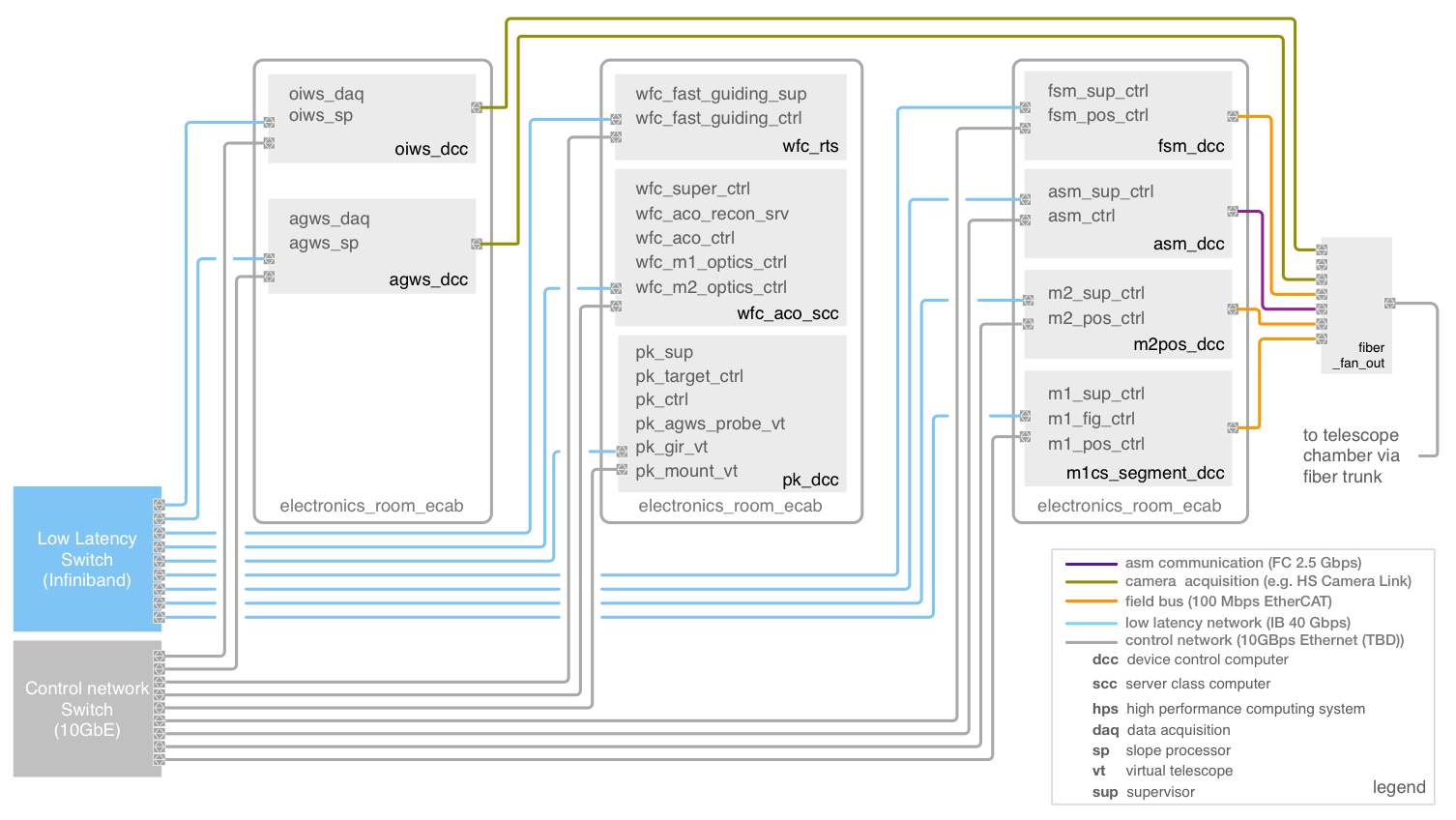
A representation of the deployment locations of the Natural Seeing WFC is
provided in the Figure below. All WFC software components run on standard
rack-mounted servers in the Electronics Room of the Summit Support Building.
All of these hardware components will be connected with both a low-latency
Infiniband network and a standard Ethernet control network. The wavefront
sensor slope processors connect to their camera systems with various
fiber-based camera protocols (e.g., CameraLink HS), allowing them to also be
located in the Electronics Room. Thus the only data connections onto the
telescope are via fiber optics.
Fig. 5.10 Natural Seeing Wavefront Control System Deployment Schematic#