9.2. Software Development Process#
The integration of the software components in the overall GMT system engineering effort follows tailored-compliance with the ISO 12207 standard [ISO12207], whereas the software development is based on an iterative Agile development process. Agile planning is based on implementing features that will be needed in the system instead of defining the tasks necessary to produce them. When planning and developing by feature, the team has a better understanding of the system and the plan is easily followed by other members of the project. The key to iterative development is to frequently, and from early on, produce working versions of the final system that have a subset of the required features. These working systems are short on functionality, but should otherwise be faithful to the demands of the final system. They are fully integrated and as carefully tested as a final delivery.
9.2.1. Domain Engineering Process#
The SWCS development process starts with domain engineering (clause 7.3.1 of ISO12207 [ISO12207]), which allows one to identify the main architectural components of the SWCS and to group them into uniform categories of subsystems, packages and components according to the cohesion of functionalities, timing requirements, and the sizes of the interfaces. The output of the domain analysis process is used as the base for the definition of the SWC Product Breakdown Structure (PBS). The PBS is based on the decomposition of the system into High Level Domains, Subsystems, Packages and Components (PBS components are captured as instances of metamodel entities).
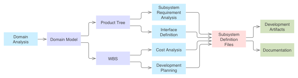
Fig. 9.1 Overall Process View#
The SWC WBS is generated in a canonical way based on the Product Tree with the addition of work packages that take into account management support activities (e.g., development or commissioning plans, component architectural prototypes). The Figure below shows the top-level structure of the SWC product tree. 1.3.3 – 1.3.5 WBS details are omitted as they are presented in previous sections. The Software and Controls WBS Report [Filg13c] document and the Software and Controls Product Tree Report [MaTr13] describe both of them in detail.
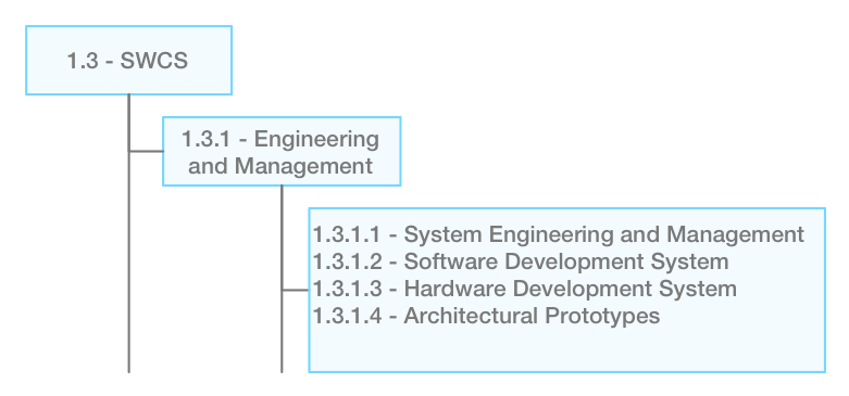
Fig. 9.2 Software and Controls System Engineering Top-Level WBS#
In addition to the work packages 1.3.2 – 1.3.5 described in previous sections the work package 1.3.1, Software and Control Engineering and Management includes all the activities and resources needed to support the software development.
At the end of this phase the following outcome is produced:
The identification of all the subsystems
The identification of the interfaces
A formal reference architecture captured in a domain model
A cost estimation
An initial definition of the backlog for the development of every subsystem.
9.2.2. Subsystem Development#
The SWC System is treated as a system of systems in terms of planning activities. The development of each SWC subsystem is organized in four sequential phases or macro-sprints in Agile terms:
Phase 1 – Subsystem specification performs the initial requirement analysis, the organization of the Subsystem in Packages and Components and the creation of the initial product backlog. “Product backlog” is a common term used in Agile management to refer to the functionality, e.g. user stories or features, that have to be developed. For control subsystems, Phase 1 generally starts after the preliminary design of the system under control. However, Phase 1 may start earlier to support preliminary design of the hardware subsystem if the necessary requirements to do so are sufficiently developed.
Phase 2 – Design sprint implements the high priority, high value, Subsystem features. The assignment of priorities to features takes into account which ones are likely to provide: better feedback about the design of the Subsystem, important information that help to identify and mitigate risks in designs (e.g., a particular algorithm that requires computing power at the limit of the proposed hardware platform), or a higher business value. Subsystem features also include hooks necessary to support eventual hardware prototypes.
Phase 3 – Construction sprint implements the bulk of the subsystem features backlog. At the end of this phase all the features necessary to perform the Factory Acceptance Testing (FAT) of the system under control have been developed, integrated, tested and deployed.
Phase 4 – AIT sprint implements the rest of the product backlog. AIT sprint includes the development of features that require most of the Components to be already implemented. It also includes potential changes as a result of the FAT.
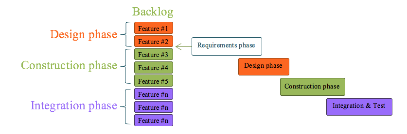
Fig. 9.3 Software Development Phases. The inception or Requirements Phase produces the initial backlog of a subsystem features. Features are prioritized and assigned to subsequent phases. Each phase is constrained by project milestones like on-site integration or factory acceptance testing.#
In this subsystem development strategy each phase can be seen as a ‘standard’ Agile project. This suits the multiyear development span of the GMT optomechanical systems. Although, initially, the software system naturally lags the hardware in design and development, the software system generally outpaces the hardware to arrive at the final integration and commissioning phase of the mechatronic system.
Each phase or super-sprint is divided into a sequence of iterations, typically of one-month duration. Iterative development allows measurements and control of progress. At the end of every iteration, a retrospective review takes place to analyze problems found during the development process and to present the results to the subsystem stakeholders. A retrospective analysis is also held at the end of every phase to analyze the features developed and to restate priorities if necessary.
It is easy to plan an entire project using standard tasks without really understanding the system being built. Agile planning is based on implementing features that will be needed in the system instead of tasks. When planning by feature, the team has a better understanding of the system and the plan is easy follow by other members of the project.
The approach of incremental delivery and the refinement of the software features map naturally to a telescope project where many of the software systems follow the design of their mechanical counterpart. The same is true about the top-tier software components that must support the operation plans of the observatory, which are also often refined during the life cycle of the project. Moreover the incremental implementation of the features provides more value or addresses higher risks that then feedback and help to better refine non-software observatory systems.
9.2.3. Subsystem Specification and Modeling#
Level 5 requirements are captured in System Definition Files (SDF). SDFs are written using a Domain Specific Language (DSL). A DSL is a computer programming language of limited expressiveness focused on a particular domain47. A DSL facilitates productivity and communication with domain experts. At the same time the use of a DSL helps to involve domain experts in building the model and the system.
The use of a Domain Specific Language (DSL) provides a formal syntax and semantics that reduces the ambiguity of the specifications. The concrete syntax is provided by the DSL, while the semantics are given by a set of models following the Object Management Group Meta Object Facility architecture. The SDFs are ASCII files that are parsed and stored in the semantic model database and processed for consistency and completeness. They are hosted in the GMT central software private repository in Github (Figure below), for access by the GMT software community and revision control. The use of Github features allows participants to comment and carry on discussions directly in the model repository.
SDF are being developed as the design of the systems under control moves forward. A first generation set has been produced as part of the Domain Engineering process. The Figure below shows the GMT model homepage on Github.
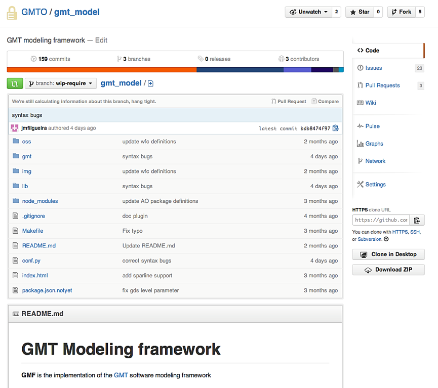
Fig. 9.4 GMT Software Github Page#
The use of SDFs enables the following features:
Subsystem build dependencies
Generation of Subsystem test configuration and test data
Subsystem software deployment
Subsystem metadata (e.g., on-line documentation, component introspection)
Integration with support tools
A method to provide inheritance mechanism to specialized specification from more general ones
An ability to define, initially, the specification based on interfaces
Systematic ways to guarantee uniform architectural design and specification based on a reference architecture optimized for the domain (observatory and telescope control).
Clear and formal feature specifications; the semantics are defined formally in a metamodel.
Storage and further processing of the specifications in a database. The specifications are available during runtime to provide introspection mechanisms.
An ability to allow fine grain changes and management of the specification files, as they are under configuration control.
Direct traceability between requirements/specification and implementation. Some tools have been developed that allow the generation of runtime scaffolding and skeletons.
Documentation support, where documents are rendered from the specification files in RST. Through the use of the Sphinx [Sphi13] package, documentation can be produced in Latex, PDF and HTML formats. Templates have been defined for most of the documents required in the SWCS Handbook. The Table below shows an overview of the existing document templates.
An ability to share and reuse specifications between developers in different organizations. All the specification files are required to be integrated in the GMT common repository, currently in Github.
Test procedures and test data generation
Subsystem integration
Stage-gate document generation
Project progress reporting
Subsystem deployment
Interface definition
Backlog generation
9.2.4. Software Quality Assurance Process#
The Software Quality Assurance process is based in the ISO/IEC 12207 Software Quality Assurance Process. The purpose of this process is to provide assurance that work products and processes comply with predefined provisions and plans. The quality assurance process is coordinated with the related Software Verification, Software Validation, Software Review, Software Audit, and Software Problem Resolution processes. The Software and Controls Handbook section on Software Engineering and Quality Assurance includes the ISO/IEC 12207 conformity Matrix for these processes.
The SWCS will implement standard processes, and utilize commercial products whenever possible, for the management of software source code, builds, releases, issue tracking and distribution. An overview of these tools, the MDE methodology and the “Agile” management process are presented in the Section 10.6 (TBA?, Software & Controls Risks).
Software Verification Process
The purpose of the Software Verification Process is to confirm that each software work product and/or service of a process reflects the specified requirements. Several techniques are employed to implement the verification process:
The capability of SWCS components to operate in on-line or simulated mode enables testing interfaces early in the development cycle.
The capability of SWCS components to operate in integrated or standalone mode enables to test components without the need of the observatory services in place. This is useful for the initial steps in the implementation of a component.
Automated tests for subsystem and component are generated from the formal specifications defined in the corresponding SDFs facilitating the traceability between requirements and tests.
The SWCS Handbook defines deliverables and policy for Factory Acceptance Testing (FAT) and Site Acceptance Testing (SAT).
In the case of critical system formal verification can be performed using Sequence Base Specification [Prow96] (SBS) or Cleanroom techniques.
Issue Management
GMTO is currently using Github’s built-in issue tracker. Issue tracking is used to identify errors and non- conformities in the implementations of software components. Issues on github contain the following fields:
Issue "issue_id",
     Title:     "foo compilation error" "Jane"
     Assignee:  "Jane"
     Label:     "bug"
     Milestone: "v1.0"
     Details:   """% gcc -Wall -pedantic foo.c error 'bar' is not defined. """
9.2.5. Software Configuration Management Process#
The purpose of the Software Configuration Management Process is to establish and maintain the integrity of the software items of the SWCS and make them available to concerned parties. The software configuration management (SCM) provides a framework to uniformly support several aspects of the software development process and delivery stages:
Source management
Release management
Build management
Deployment management
The SCM adopts a paradigm of convention over configuration, allowing different 3rd-party tools to interact somewhat transparently with minimum development needed to build a framework.
Source Management
GMTO uses Git [Chac14] for source code management. As stated by the developer (git-scm.com), “Git is a free and open source distributed version control system designed to handle everything from small to very large projects with speed and efficiency.” Git features include cheap local branching, convenient staging areas, and multiple workflows.
GMTO repositories are hosted on Github, which offers private repositories for organizations at modest cost. Github offers additional features detailed in the following sections, and provides an API to manage resources (repositories, user profiles, organizations, etc.) programmatically. Hosting on the Cloud alleviates several IT logistics burdens compared to a self-hosting solution: VPN and/or private network, backup, availability, authentication etc. As a distributed system, Git makes each working copy effectively function as a remote backup of the codebase and of its change history, providing inherent protection against loss. Additionally, a backup of a master local copy is store for enhanced safety.
Release Management
Release management of the individual modules is handled by tags. A simple “semantic versioning” is established using the following tag convention: major.minor[.build[.revision]], where:
Major number is increased when there are significant jumps in functionality, possible break in API backward compatibility
Minor number is incremented when only minor features or significant fixes have been added
Build is optionally alpha, beta, rc (release candidate)
Revision number is incremented when minor bugs are fixed Additional semantics possible: odd-even system, etc.
Release management of the entire system (i.e., all the collection of software and configuration), is provided by the GMT model. Each individual subsystem defines release information and keywords to allow the creation and re-creation of well-identified, repeatable, release “snapshot”.
Tools will allow querying and updating of the model. In its simplest form a text editor is enough, but more advanced capabilities will allow one to generate dependency trees and deployment information, to identify and resolve conflicts, to check runtime version, to upgrade mechanism automation, to sign-off feature working with SCM, etc.
Build Management
A standard software build facility is provided, including directory structure, environment, configuration files, Makefiles, spec file, distutil file, etc. as applicable.
Deployment Management
GMTO uses rpm and yum for software package management on its Linux platform. Workflows:
Extract release tag from model
Checkout source from git
Build rpm
Update yum server repository
Push update notification to update server and project maintainers
Project maintainer coordinates and deploys new software
9.2.6. Software Document Management Process#
The purpose of the Documentation Management Process is to develop and maintain the recorded software information produced during the SWCS development process. Agile techniques favor the production of working code over documentation. However, a minimum set of documentation is necessary to address GMT specific characteristics:
GMT is a multidisciplinary project that requires communication with engineers from disciplines other than software.
GMT requires producing “stage-gate” documents to support project reviews.
The GMT documentation system tries to address both issues, without creating a burden on the software development process. The strategy is to provide a high-level handbook that helps to navigate the software system and to provide mechanisms to generate documentation from specification files.
The Software and Controls Handbook provides a one-stop document to address all the information necessary for the development of GMT software and control systems. The Handbook includes:
An overview of the SWCS Reference Architecture
A set of requirements that all the subsystems have to meet
A list of software and hardware standards
A catalog of recommended components
A set of recommendations and guidelines
An overview of the development strategy
The documentation of the entire software system is automatically generated from subsystem and model definition files (SDFs and MDFs), which, at every moment, are synchronized with the specification and the design of the system. At the same time the method reduces the amount of work necessary to produce documents. The documentation is extracted from the specification files and rendered into reader-friendly formats using the Sphinx76 package. LaTeX, PDF, html and RST formats are available. The table below provides a documentation overview of the available templates.
Component |
Documents |
Description |
|---|---|---|
System |
SWCS WBS Dictionary |
List and description of all the Software and Controls WBS items |
SWCS Product Tree Report |
List and description of all the Software and Controls Configuration items |
|
SWCS Cost Report |
Cost estimation organized by subsystem, package, component, and project stage |
|
SWCS Project Progress Report |
SWCS development progress metrics, includes burnout charts for all the subsystems |
|
Subsystem |
Subsystem Specification Report |
Subsystem Specification Report |
Subsystem Design Report |
Subsystem Design Report |
|
Subsystem Backlog Report |
Subsystem Backlog Report |
|
Subsystem Progress Report |
Subsystem Progress Report |
|
Subsystem AIT Test Plan |
Subsystem AIT Test Plan |
|
Subsystem AIT results |
Subsystem AIT results |
9.2.7. Software Integration Process#
The purpose of the Software Integration Process is to combine the software subsystems and software components, producing integrated software system, consistent with the software design, that demonstrate that the functional and non-functional software requirements are satisfied on an equivalent or complete operational platform. The SWCS uses a Continuous Integration (CI) system that ensures that integration problems are discovered early in the development cycle. Both software packages developed by the PO and by partner institutions are integrated and tested early in the project. SDFs provide all the information necessary to build and integrate the different subsystems, which facilitates the implementation of a continuous integration system. OTS CI tools like Jenkins* provide ready to use solutions.
Partial hardware simulators are used during the initial development of Device Control Subsystems to identify issues with field interface electronics before the integration with the final hardware devices.
9.2.8. Development Workflows#
As part of the domain engineering process a set of development workflows has been identified. While the ISO/IEC 12207 process is generic, Workflows are specific to the GMT project. They define concrete step-by-step processes for the developing of the most frequently utilized software components (e.g., Controller Development Workflow).
The development Workflows are also specified using SDFs. This allows the use of the same tools for generating documentation and the support for improvement, once the GMT software community starts developing software. The table below provides an overview of the main SWCS Development Workflows:
Components |
Workflows |
Input |
Output |
Roles |
|---|---|---|---|---|
System |
Domain Analysis Requirement Analysis Cost Estimation Development Planning AIT Planning |
SLR document OCD document L2 Common documents |
SWCS L3 requirements SWCS WBS Dictionary SWCS Cost Report SWCS Handbook SWCS Development Plan SWCS Metamodel/Model SWCS Architecture Report |
System Architect SWCS Stakeholders |
Subsystem |
Subsystem Specification Subsystem Sprint Planning Subsystem AIT Definition |
SWC Metamodel/Model SWC Architecture Report |
Subsystem Definition Files Subsystem Implementation Subsystem Iteration Plan |
System Architect Subsystem Developer Subsystem Stakeholders |
Package |
Control Package Development Data Processing Package Package Development Framework Development |
Subsystem Definition Files |
Package Definition Files Package Implementation |
System Architect Subsystem Developer Subsystem Stakeholders |
Component |
Controller Development Pipeline Development UI Panel Development Sequence Development |
Subsystem definition Files Package Definition Files |
Component Definition Component Tests Component Implementation |
Subsystem Developer Subsystem Stakeholders |