5.4.3. Coordinate Systems and Transformation Flow#
There are several coordinate systems in common use in astronomy. When an
astronomer specifies a target coordinate, that information often needs to be
transformed into another system before it can be used to command the telescope
to a [Az, El] location and for telescope tracking. The general implementation
strategy for pointing, tracking, and guiding involves two transformations.
First the transformation of target coordinates from celestial [α, δ] (or [Az,
El]) into an observed direction [Az, El] to point the telescope, accounting for:
coordinate systems, space motions, Earth motions, refraction, and other
non-instrumental terms. Next the pointing kernel transforms observed [Az, El]
direction into mechanical encoder direction for the mount, via a “pointing
model” to account for: misalignment of the mount, tube flexure, instrument
flexure, etc., as well as user desired pointing origin, and offset from base
(e.g., for scanning).
Fully specifying a target’s location in the sky requires the following
information:
Coordinates – In [α, δ] or [Az, El].
Coordinate system – e.g., whether the [α, δ] is in FK4, FK5, or Topocentric
apparent system.
Equinox – e.g., B1950.0 or J2000. Before 1984, the equinox is usually in
the B system, whereas on or after 1984, it is usually in the J system. The
default is to assume J2000, FK5 coordinate system.
Epoch – For objects that have proper motions, this is the time-zero from
which proper motions are calculated. The epoch is generally specified as a
given year (e.g., 1964.25).
Proper motion – There are various units for proper motion (arcsec yr
-1, arcmin century -1, etc.). By default proper motion is
zero.
Parallax – Usually has units of [arcsec], and the default value is zero.
Radial velocity – Usually has units of [km s -1], and the default
value is zero.
Supported coordinate systems and the subsequent transformation flow are
described below.
Coordinate Systems
The coordinate systems that will be supported are listed and described in
the Table below; the default will be ICRS:
Table 5.11 Coordinate Systems Supported by the TCS#
Coordinate System
Description
FK4 [α, δ]
Often referred to as the B1950 (Besselian epoch 1950.0) coordinate
system, this mean equatorial system pre-dates the 1976 IAU resolutions.
FK5 [α, δ]
Often referred to as the J2000 (Julian epoch 2000.0) coordinate system,
this mean equatorial system post-dates the 1976 IAU resolutions.
ICRS [α, δ]
The International Celestial Reference System (ICRS) is the current
standard adopted by the International Astronomical Union, beginning
1998. The origin is at the barycenter of the solar system with the axes
fixed in space, and corresponds closely to FK5 J2000 to within ~30
mas for an object. [Default]
Topocentric
apparent [α, δ]
Mostly used for solar system targets when inputs come from solar system
ephemeris. programs where parallax (annual and diurnal), planetary
aberrations, and their motions (i.e., tracking rates in [α, δ]), would
already have been pre-computed.
Observed [Az, El]
Used when another program, external to the TCS, has made all the
transformations necessary.
Mount [Az, El]
Mostly used for engineering and calibration applications. The relation
between the Mount [Az, El] and observed [Az, El] is given by the
pointing model.
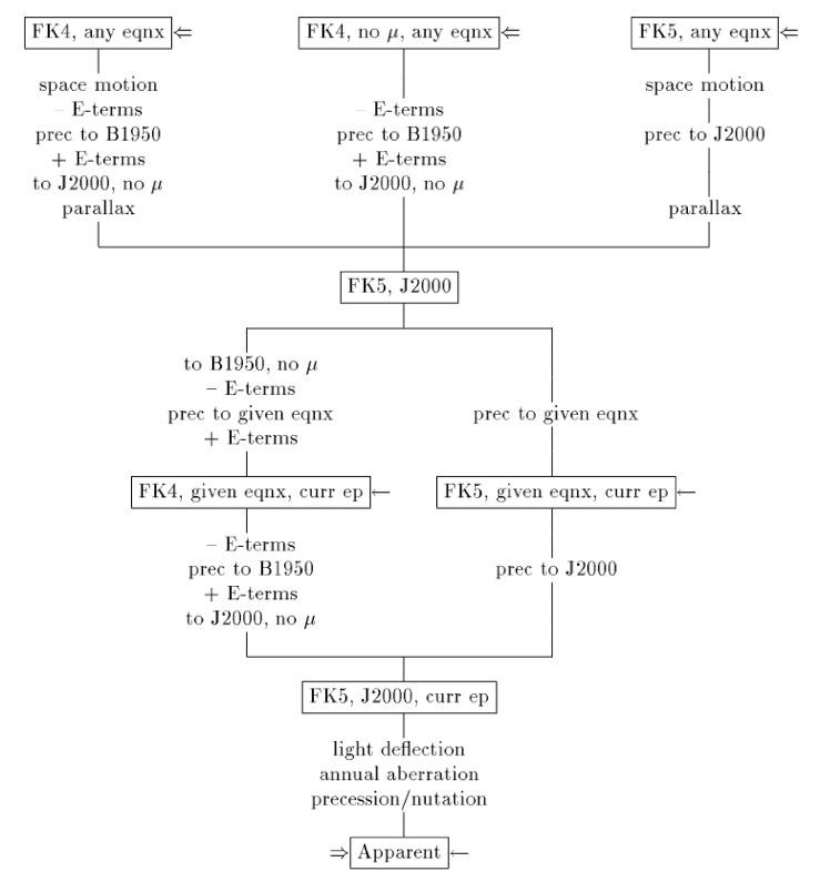
Celestial Coordinate System Transformation Flow
Given a coordinate [α, δ] in any celestial coordinate system by an astronomer,
the TCS will convert it to FK5, J2000, and the current epoch, before producing
the apparent [α, δ] used to aim the telescope. The transformation flow and the
terms to correct for are given in the following
Figure. The TCS uses SLALIB [Wall12b] to
transform celestial coordinates into an apparent direction to point the
telescope. New coordinate systems will be supported as interests and needs
arise by upgrading or replacing SLALIB with another tool.
The above Figure shows the transformation flow taking coordinates from one
reference frame to another, adapted from Wallace [Wall96][Wall12b]. All
input coordinates are eventually converted into FK5, J2000, current epoch,
before final conversions to apparent [α, δ] to point the telescope.
Transformation of Celestial System to Mount Encoder Positions
The TCS/MCS Pointing Flow Figure (below) shows
the steps taken to convert celestial coordinates [α, δ] into instrumental
direction [Az, El] and rotator angles that the mount servo system needs to
position the telescope. There are two flow directions, distinguished by how
often the information needs to update: downward (slow, 20 Hz) and upward
(fast, > 20 Hz). The downward direction (upper half of Figure) first transforms
target celestial coordinates into a corresponding line-of- sight [Az, El]
coordinate, correcting for terms that are independent of the telescope mount.
Those terms include: aberrations (annual and diurnal), light deflection,
precession/nutation, Earth’s rotation, motion around the sun, parallax, and
refraction.
Next, additional errors factor in via pointing models (blue box, and see
Virtual Telescope Figure (below)), such as
mount non-perpendicularity and tube flexure. A pointing model consists of a
set of coefficients that accounts for non-perpendicularity of the telescope
axes, imperfections in alignment, flexure, or other mechanical imperfections.
Lastly, to position the target coordinate at the user desired locationon the
science detector (i.e., a slit or image pixel), it is necessary to offset the
pointing origin to that location, which involves adjusting the rotator angle
and position offset relative to the optical telescope axis. The above
transformations result in the actual demand, angle [Az, El] for aiming the
telescope mount.
In contrast, upward transformations (lower half of Figure) take place at much
higher frequencies (>20 Hz), the purpose of which is to react to fast
mechanical positioning demands, such as target scanning, tip-tilt guiding,
wind perturbations, AO closed loop operations, image centroiding, and encoder
errors. The telescope Az/El servo system compares the mount demand (downward
flow) versus that achieved (upward flow) to determine the appropriate actions
for the mount.
Fig. 5.7 TCS/MCS Pointing Flow. The blue box is the telescope pointing model,
details of which are elaborated in the Figure below on the Virtual
Telescope. Horizontal arrows indicate the
different pointing coordinates: Mean [α, δ], Apparent [α, δ], Topocentric
[-h, δ], Observed [Az, El], and Mount [Az, El], users may specify and where
they enter the flow in the transformation.#
The TCS/MCS pointing flow, above, adapted from Wallace [Wall12a], shows the
transformation flow that takes target positions from the TCS (e.g., celestial
coordinates [α, δ]) into mount encoder demands delivered to the MCS servo
systems (in small box). Details of the pointing model, blue box, are
elaborated in the Figure below on the Virtual
Telescope.