The pointing and tracking for the GMT will follow a similar scheme as that used
by some of the monolithic and segmented telescopes currently in operation (e.g.,
Magellan, VLT, Keck, GTC). The TCS does not manage image stacking of the seven
mirror segments individually. That responsibility falls to the WFCS subsystem,
which performs optical collimation, mirror figure shaping, and phasing of the
seven M1 and M2 segments. Each observing mode (LTAO, NGSAO, natural seeing) has
its own WFCS control loop. If there are residual, time-averaged, tip-tilt values
from M1 and M2, the WFCS offloads the values to the TCS, which causes the mount
to reposition. Doing so cleanly separates mount control from active optics and
AO so that the TCS needs only to have a conventional scheme for telescope
pointing. From the standpoint of telescope pointing, tracking and guiding, it
therefore makes no practical difference whether the observing mode is natural
seeing (using fast tip-tilt M2) or AO (using ASMs). Details of telescope
collimation and phasing for the different observing modes (natural seeing,
NGSAO, GLAO, LTAO) are discussed in Wavefront Control System.
Telescope tracking, pointing, and guiding, follow the schematics shown in the
three Figures below, and summarized here:
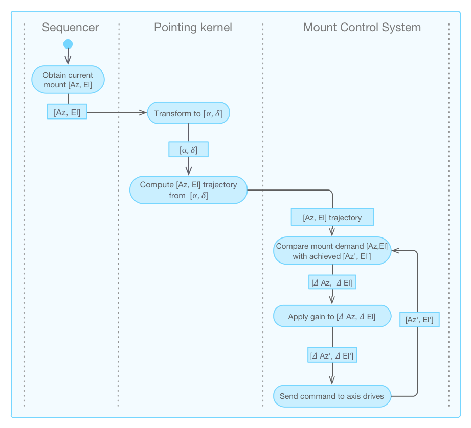
Sky Tracking -
When the telescope operator initiates telescope sky tracking
(Figure below), the pointing kernel transforms
the current mount location in [Az, El] into a sky coordinate in [α, δ],
then generates an [Az, El] trajectory to follow the sky motion (details of
coordinate transformations are discussed below). The stream of
coordinates produced by the pointing kernel feeds into the mount control
system (MCS) servo loop. The servo loop then compares the mount [Az, El]
position with the time-stamped demands and moves the mount so as to
minimize the difference, i.e., the error signal. When the MCS receives a
new coordinate the current one is immediately discarded. Details of the
MCS are presented in the Telescope Chapter.
The pointing kernel also generates coordinate streams for different
sky-tracking modes using the virtual telescopes, such as non-sidereal
tracking, drift scanning, and maintaining the pointing origin at a fixed
[α, δ] with the rotator turned off, or with the instrument fixed at a
constant position angle. Doing so requires coordinating the rotation of
the GIR as well as rotation/translation of the telescope mount axes, all
of which are performed by TCSpk.
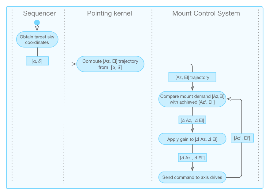
Pointing - Like with telescope tracking, the act of pointing the mount
utilizes only mount encoder information. As shown in the Figure
below, to point to a new location in the sky, the
user provides a coordinate [α, δ] or [Az, El] to the TCS. The pointing
kernel translates the input coordinate into mount [Az, El] demands. Upon
receiving the demands, the MCS servo loop repositions the mount. If the
telescope is already in tracking mode when it arrives at the new location,
the mount motion continues along the tracking trajectory. Without
sky-tracking, all mount motion would come to a stop as soon as the mount
arrives at the demanded location. Details of the telescope pointing
sequence are provided in the Operation Concept Definition Document (OCDD)
GMT-AO- REF-00244 [Tran13].
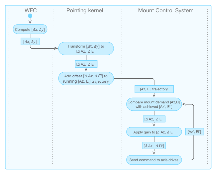
Autoguiding -
The process of autoguiding is shown schematically in the Figure
below; details of the sequences involved in setting up
autoguiding are provided in the OCDD. Like with telescope tracking, the
pointing kernel is responsible for producing trajectories based on a given
[α, δ] coordinate and instrument orientation. The responsibility for
calculating fine corrections using guide stars falls to the Wavefront
Control System, which decides whether to apply the translational motions to
the mirror optical assembly or to offload them to the telescope mount via
the pointing kernel. In this scheme, the telescope pointing kernel is
oblivious to whether the offload is due to autoguiding or for other reasons.
Offloads to the pointing kernel from the WFCS are delivered to the pointing
kernel as guiding corrections, from which the pointing kernel produces an
appropriate trajectory for the MCS servo loop.