5.4.4. Virtual Telescopes and the Telescope Pointing Model#
The concept and use of a Virtual Telescope was introduced earlier, as one of
the three main components that make up the Telescope Pointing
Kernel. To review, the purpose of the virtual
telescope is to make all the necessary coordinate transformations and
mechanical correction so the telescope can point accurately to a command
position in a manner transparent to users by hiding the complexities. In
reality, what happens “behind-the-scene” when an observer commands the
telescope to to a position in the sky is given by the Pointing Flow
Figure (above) and the the Virtual Telescope
Figure (below). Inside the Virtual Telescope is a
pointing model that handles particulars in the telescope mount orientation and
optical geometries (blue box in Figure).
The positional astronomy transformations from celestial coordinates into
observed direction is well-established and will use SLALIB [Wall12b].
Mechanical errors, misalignments, and flexure mapping/corrections will be
implemented using TCSpk [Wall12a] and diagnosed using TPoint Software
[Wall94].
Virtual telescopes with different focal positions can exist at the same time,
which enables fast dithering, fast re-positioning to transfer a target image
from one instrument to another and the ability to hold a sky target fixed at a
specified position and orientation on an instrument even as the rotator turns.
The virtual telescope generates mechanical demands (Az, El, rotator angle) to
the mount encoders to reposition the telescope. Finally, the virtual
telescope allows for easy updates to the pointing model without having to
modify the source code for the pointing kernel.
Each focal station that has an instrument, including all wavefront sensors,
engineering cameras, and science instruments, will have at least one virtual
telescope and a pointing model. It is not unusual for an instrument to have
multiple virtual telescopes depending on the purpose, such as for generating
rotator and mount demands separately while the telescope is slewing.
The pointing model (blue box in Figure) in
the virtual telescope accounts for mechanical or structural imperfections,
such as telescope flexure, mount axis non-perpendicularity, encoder errors,
instrument misalignment, encoder errors, etc. Its position in the flow of
coordinate transformations is shown as blue boxes in the Figure above
(Pointing Flow) and Figure below (Virtual
Telescope). The output of the virtual telescope,
after accounting for the pointing model, is a trajectory for mount and rotator
encoder demands which is delivered to the mount and rotator control servo.
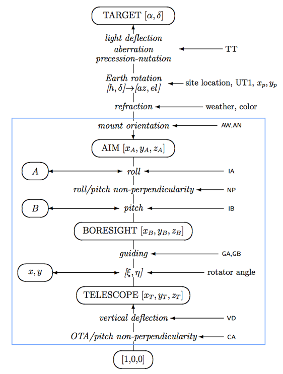
The TCS/MCS Pointing Flow Figure (above) shows
the coordinate transformation flow in natural seeing observing mode
Fig. 5.8 Virtual Telescope and Pointing Model (blue box). Details of the target
coordinate transformation (the first 4 items in the figure) are given in
the upper half of the TCS/MCS Pointing Flow.#
The above Figure shows the “Virtual Telescope” and transformation terms that
make up the pointing model; figure taken from Wallace [Wall12a]. The
telescope pointing model (blue box) typically consists of 10-20 correction
terms, here summarized into 7-terms: IA (roll), IB (pitch), VD (vertical
deflection), CA (optical telescope axis/pitch non-perpendicularity), NP
(roll/pitch non-perpendicularity), AW and AN (roll axis misalignments). GA
and GB are guiding corrections to the steady telescope tracking rate.