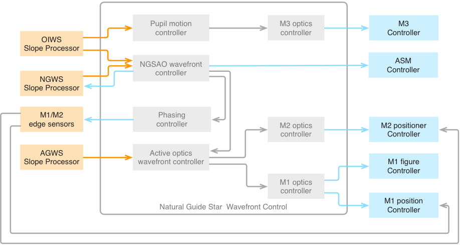
5.5.2. Natural Guide Star Adaptive Optics (NGSAO)#
A simplified block diagram of the NGSAO WFC is presented in Figure
5.11. There are six main control loops operating
simultaneously:
The NGSAO Wavefront Controller controls the ASM based on NGWS measurements.
The NGSAO Wavefront Controller updates the slope zero-points of the NGWS to
correct any aberrations measured by the OIWFS.
The M1 and M2 Edge Sensors control the relative positions of the M1 and M2
outer segments with respect to the center segments.
The Phasing Controller updates the M1 edge sensor setpoints based on the
average ASM segment piston.
The Active Optics Wavefront Controller controls field-dependent aberrations
based on AGWS measurements.
The Pupil Motion Controller adjusts the tilt of M3 to maintain the pupil
centered on the instrument.
In addition to these main feedback loops, there are several offloads between
controllers. For example the NGSAO Wavefront Controller offloads the
time-average segment piston and tilt to the Phasing Controller, and the average
surface figure of the ASM to the Active Optics Wavefront Controller.
Fig. 5.11 NGSAO Wavefront Control System Simplified Block Diagram#
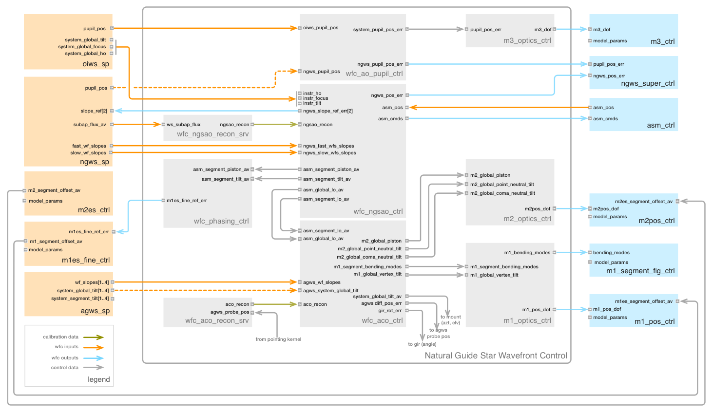
Figure 5.12 presents a more detailed block
diagram of the NGSAO WFC, with all of the real-time components currently
envisioned. External components with interfaces to the WFC (e.g., sensor slope
processors and mirror controllers) are also represented. Ports are identified
with the input or output data type, and data flow with arrows. Telemetry is not
explicitly shown, as it is provided as a system service to every component.
Component Descriptions
Fig. 5.12 NGSAO Wavefront Control System Detailed Block Diagram#
A list of the NGSAO WFC components is provided in the Table below. A
description of the most critical components is given below, followed by an
identification of the connections between them.
Note that wavefront aberrations have been identified using the following
nomenclature:
Global aberrations are defined over the full GMT pupil, while segment
aberrations are defined over each segment.
System aberrations represent a measurement of the full telescope optical
system, while M1, ASM, etc., aberrations represent only the contribution of
one optical surface.
Temporal averages of an aberration are identified as aberration_av.
At the present time, Zernike polynomials [Noll76] are used as the basis set
throughout the WFC (with the exception of ASM and M1 figure control) due to
their simple relationship to rigid body motions. Karhunen-Loeve modes which
replicate Zernike modes in the low orders may be considered in the future.
Table 5.18 NGSAO Wavefront Control System Components#
Component Name
Description
Software Package
wfc_ngsao_ctrl
NGSAO Wavefront Controller
wfc_ngsao_pkg
wfc_aco_ctrl
Active Optics Controller
wfc_common_pkg
wfc_ao_pupil_ctrl
AO Pupil Motion Controller
wfc_common_pkg
wfc_phasing_ctrl
AO Phasing Controller
wfc_common_pkg
wfc_ngsao_recon_srv
NGSAO Reconstructor Server
wfc_ngsao_pkg
wfc_aco_recon_srv
Active Optics Reconstructor Server
wfc_common_pkg
m1_optics_ctrl
M1 Optics Controller
wfc_common_pkg
m2_optics_ctrl
M2 Optics Controller
wfc_common_pkg
m3_optics_ctrl
M3 Optics Controller
wfc_common_pkg
NGSAO Wavefront Controller
The NGSAO Wavefront Controller (wfc_ngsao_ctrl) converts the pyramid WFS
signals sent by the NGWS Slope Processor (ngws_sp) to an actuator command
vector destined for the ASM Controller. The algorithms of this primary
control loop are described in detail in Section 8.8.1 [Bouc13b]. As the
interface to the ASM Controller is in terms of absolute actuator position,
the wfc_ngsao_ctrl component provides the integrator and must receive the
actuator position after the previous step by the ASM. Maintaining the last
commanded position in memory is not sufficient, due to the safety checks and
clipping performed by the ASM global controller. This architecture has been
selected primarily for consistency with the LTAO/NGLAO pseudo-open loop
control strategy.
In addition to the primary control loop, the wfc_ngsao_ctrl component
performs several offloads to other WFC components at <1 Hz, calculated by
projecting the time-averaged difference between the ASM actuator positions
and their calibrated “flat” positions onto various modes:
Segment piston and tilt are sent to the Phasing Controller.
Global tilt is sent to the pointing kernel and used as the telescope
guiding error.
Global Zernike modes Z4, Z7, and Z8 (focus and coma) are sent to the
Active Optics Wavefront Controller, and used to reposition the ASM.
M1 segment bending modes [Smit13] 1-45 are sent to the Active Optics
Wavefront Controller, used to offload any M1 figure errors that have
been compensated by the ASM.
The wfc_ngsao_ctrl component receives residual error measurements from the
OIWFS Slope Processor, allowing it to compensate changing non-common path
(NCP) wavefront error. While it is typical in current-generation AO systems
to perform the high-order NCP calibration in daytime, dynamic calibration
will be necessary in the NGSAO and LTAO modes due to the rotation of the
pupil on the Instrument Window, which will be distorted by varying
atmospheric pressure (see Section 8.5.1.1 [Bouc13b]). Observations of a
non-sidereal science target using a nearby fixed NGS will suffer from
additional varying NCP aberrations as the NGS footprint tracks across the
Instrument Window.
Tilt and focus flexure compensation will typically be performed at <1 Hz,
and any faster input data stream will be averaged down. These modes will be
sent to the NGWS Supervisor component for correction by the translation
stages or modulation mirror. NGWS slope zeropoints will be updated at <0.1
Hz. The wfc_ngsao_ctrl component must rotate the instrument aberrations to
the NGWS reference frame, and convert them to an offset in the Sx and Sy
signals. This offset is then added to an offset buffer in the ngws_sp
component.
The input and output ports of the wfc_ngsao_ctrl component are listed in
the following Table:
Position update for NGWS patrol stages or
modulation mirror.
mas
0.012
1
Output
ngws fast
slope ref err
Update of NGWS fast channel slope zero-points
pixel
43.5
1
Output
ngws slow
slope ref err
Update of NGWS slow channel slope zero-
points.
pixel
43.5
1
Output
asm cmds
ASM actuator commands.
nm
18.8
2000
Output
Active Optics Wavefront Controller (NGSAO Mode)
The Active Optics Wavefront Controller (wfc_aco_ctrl) is responsible for
maintaining the collimation and focus of the telescope, and controlling the
figure of the M1 segments. While the NGWS and ASM minimize the wavefront
error on-axis, the AGWS will detect any off-axis aberrations resulting from
M1 figure errors being corrected at M2, and vice versa.
The inputs to the wfc_aco_ctrl component are the AGWS centroids, offloads
from the NGSAO Wavefront Controller, and a reconstructor matrix. The four
AGWS probes can each be configured in any of 3 modes, measuring system
global tilt, system segment tilt, or 25×25 Shack- Hartmann centroids. In the
NGSAO mode, one probe would typically be configured to measure global tilt
(used for acquisition, but ignored thereafter), and three probes configured
as Shack-Hartmann sensors to control field-dependent aberrations and GIR
rotation. The AGWS WFS centroid vector is multiplied by a reconstructor
matrix to derive the coefficients of various output modes, which correspond
to degrees of freedom of the available optical compensators. The controlled
modes are listed in Table 10-25 [TBA], and in the general case include M2
segment and global rigid body motions, M1 global tilt, and up to 45 bending
modes of each M1 segment. Updates to the AGWS probe position and GIR
rotation angle are also computed.
In the NGSAO and LTAO modes the wfc_aco_ctrl component maintains the ASM
actuators near mid-range by adjusting telescope collimation and focus (M2
global rigid body motion), but does not control M2 segment rigid body
motions. Doing so could compromise the phasing of the segments, which are
instead controlled directly by the M2 Edge Sensors.
The wfc_aco_ctrl component also corrects field-dependent aberrations not
detected by the AO wavefront sensors. If the ASM internal metrology were
perfect, then the offload of the average actuator positions projected onto
the M1 segment bending modes should leave the ASM with the ideal shape over
long timescales. However, any reference body flexure or drift in the
internal capacitive sensors will lead to quasi-static aberrations on the ASM
face sheets with compensating aberrations on the M1 segments, resulting in
field-dependent aberrations. Simulations of the WFC demonstrate that
low-order aberrations up to Z10 can be distinguished between M1 and M2
segments with 3 AGWS WFS (see Section 6.12.2.5 [John13]). The
wfc_aco_ctrl component will correct these by applying a fixed offset to
the M1 segment figure and telescope pointing. This is mathematically
equivalent to updating the ASM reference shape and allowing the ASM to
offload to this new shape.
The outputs of the wfc_aco_ctrl component are offset commands to the M1
and M2 optics controllers (m1_optics_ctrl and m2_optics_ctrl), and
updates to the pointing kernel, which control the AGWS probe locations and
GIR angle.
AO Phasing Controller (NGSAO Mode)
The Phasing Controller (wfc_phasing_ctrl) in the NGSAO mode provides updates
to the M1 and M2 edge sensor control points. The relative position and tilt
of the M1 and M2 segments is controlled at low bandwidth (<1 Hz) by the M1
and M2 edge sensors in closed loop with the M1 and M2 segment positioners.
Meanwhile, the NGWS detects any residual segment piston and tilt at high
bandwidth (>>10 Hz), and compensates this error with the ASM actuators. The
role of the wfc_phasing_ctrl component in the NGSAO mode is therefore only
to offload the time- average segment piston and segment tilt from the ASM
actuators to the edge sensor setpoints.
Since the NGWS sees only the system segment piston and tilt error, it is not
possible to determine whether it is M1 or M2 that has caused it. Offloading
small amounts (microns) of segment piston to the wrong mirror has no
negative impact, but segment tilt on the wrong mirror will cause field-
dependent segment piston (see Section 8.1.5 [Bouc13b]). We expect the M2ES
to be an order of magnitude more stable than the M1ES over long timescales,
due to their construction of Zerodur and the lower sensitivity of capacitive
sensors to environmental effects. The time-averaged ASM segment piston and
tilt will therefore be offloaded to the M1ES setpoints, with the M2ES left
unchanged.
The input and output ports of the wfc_phasing_ctrl component are listed in
Table 10-26 [TBA]. The ports used in the NGSAO mode are identified in the
last column.
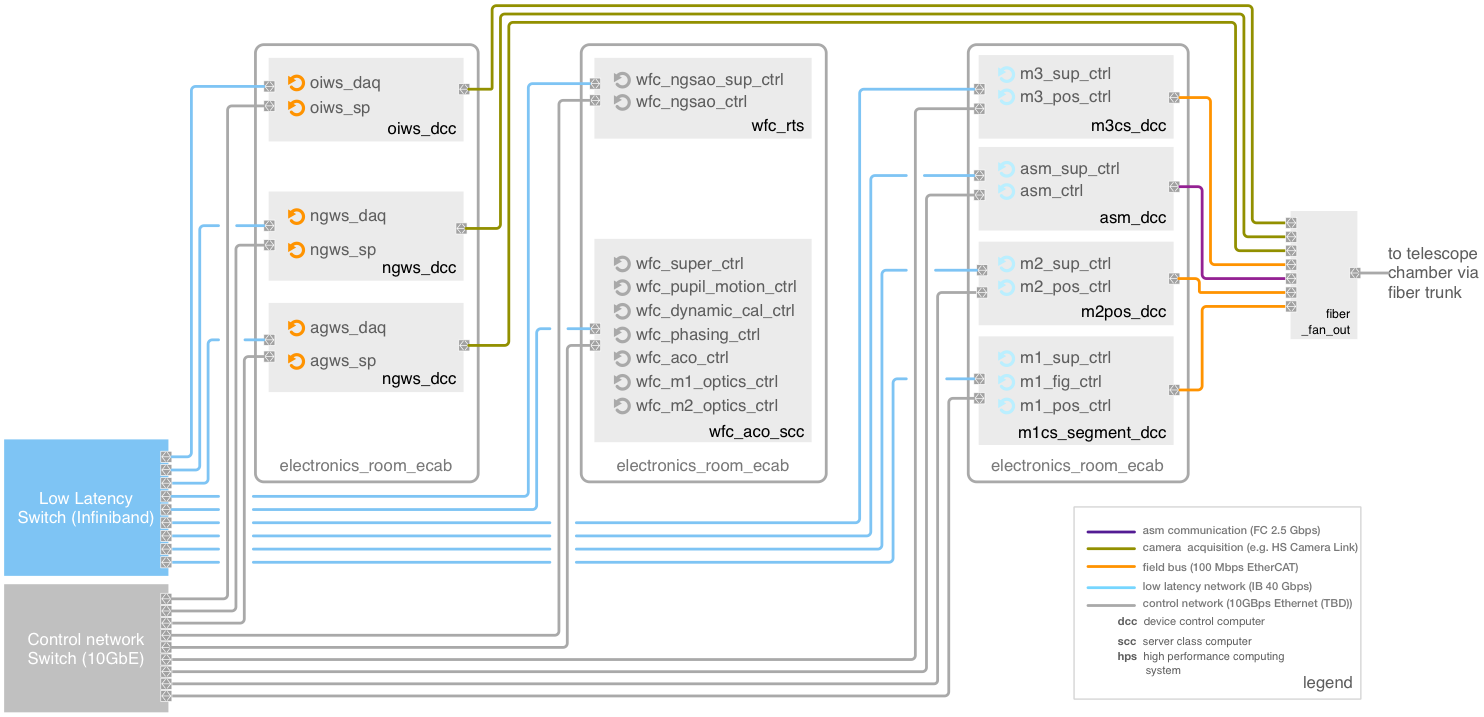
Deployment
A representation of the deployment locations of the NGSAO WFC is provided in
Figure 5.13. Most WFCS software
components run on standardized rack-mounted servers in the Electronics Room
of the Summit Support Building. The two exceptions which require specialized
hardware are the ASM Master Control Unit crate on which the ASM Controller
runs, and the AO Real-time Computer System (AORTS) which includes the NGSAO
Wavefront Controller.
The current baseline design calls for a single AORTS (identified as wfc_rts
in Figure 5.13) to be re-used for
all the observing modes. The RTS will likely be composed of multiple server
nodes in a small high-performance computing cluster (see Section 8.8.4
[Bouc13b]), and a smaller number of computing nodes might be used in the
less demanding modes (e.g., NGLAO).
Fig. 5.13 NGSAO wavefront control system deployment diagram#
Simulations
No complete simulations of the NGSAO wavefront control system with all of
the control loops presented in this section have yet been performed.
However, the fast NGSAO control loop (Loop A, see Section 8.8.1 [Bouc13b]),
the edge sensor and Phasing Controller behavior (Loops C and D, see Section
10.3.2.5.3.3), and the interaction between the active optics controller and
NGSAO/LTAO on-axis wavefront compensation (Loop E) described in this section
have been independently simulated. Active Optics Controller simulations can
be found in Section 6.12.2.5 [John13].