2.1. Requirements Document Tree Structure#
Figure 2.1 presents an overview of the GMT requirements document structure, as seen from the standpoint of the SWCS. The requirements flow-down is part of the Systems and Software Engineering process, explained later in Systems and Software Engineering.
As illustrated in Figure 2.1, Level 3 is the top-level hierarchy for the SWCS, the requirements for which flow down, directly or indirectly, from the following documents:
System Level Requirement Document (SLR) that defines the main optical, electrical, and mechanical systems that make up the observatory, as well as their high level functional and performance requirements.
Operations Concept Document (OCD) that defines the technical operations and activities associated with the observatory that are necessary to carry out science operations and maintenance of the GMT.
Common Documents that provide information that applies to the development of requirements and interfaces.
The high-level requirement documents for all other major GMT systems (Telescope, AO, Instruments, Enclosure and Facilities) also originate at Level 3 alongside the SWCS. For all those systems, the requirements are developed by systems engineering through error budgets analysis and flow down from Level 2. Performance budgets (e.g., pointing) as well as allocations (e.g., utilities, maintenance time) are parceled out to the Level 3 subsystems, so as to meet the overall functional and performance goals established in the SLRD (Level 2), the OCD, and ultimately the Science Requirements Document (SRD) [JoMK13].
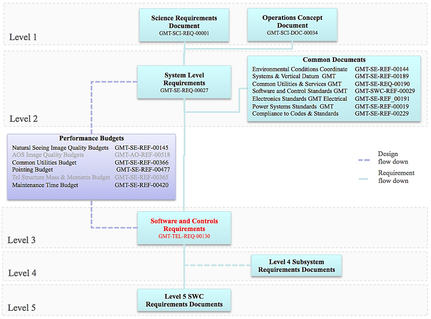
Fig. 2.1 Software and Controls Requirements Flow Down#
The Software and Control Standards [Filg13b] (also referred to as the SWCS Handbook) describes the reference architecture, standards and the recommended practices for specifying, developing and integrating the software and control subsystems.
At Level 4, the major GMT systems, (e.g., telescope, enclosure) are partitioned into subsystems (e.g., M1, ASM, GIR, LGSS) that need to be controlled by the SWCS. There, the subsystem performance and functional requirements are defined, and performance budgets are parceled out.
The main SWCS subsystem requirements are defined at Level 5 to enable flow down from Level 4 requirements. As an outcome of Level 4 subsystem architectural design, interfaces between Level 5 subsystems are identified, and requirements involving functions implemented in software are allocated to Level 5 SWCS subsystems like for example the M1 control system, the Adaptive Secondary Mirror Control System, as well as other cross-cutting subsystems like the Alarm Service.