3.4. Software Deployment#
The SWCS software Components are deployed in a distributed set of computers connected by the control network. The deployment architecture follows a layered approach (See Deployment Architecture Figure below):
The Device Layer is the system under control. It includes the optomechanical devices of the telescope.
The Fieldbus Layer enables the interface between the control subsystem and the subsystem under control. The Section on Field Device Interface Technology describes how EtherCAT and other standard buses are used to implement this interface.
The Supervisory and Control Layer implements the control of the different subsystems as explained above. The controllers are deployed in the GMT standard hardware platform. All of them are connected to the control network. The internal architecture of the control subsystems is presented in the Section on the Telescope Control System. This layer also includes the Wavefront Control and Pointing Kernel subsystems that implement the system behavior of the telescope. The Section on Computing Platform describes the computing platform options used for the deployment of device control subsystems.
The Observatory Layer includes the software components that implement observatory operations and services. These components are deployed in standard server class computers that support a cloud-like infrastructure (e.g., OpenStack). The optimal deployment of these subsystems will depend on the detailed Observatory Operation Plans. The platform may be distributed in different geographic locations or even partially deployed in cloud-like infrastructure. This is an area where it is wise to allow flexibility in deployment schemes because the technological infrastructure is likely to evolve before the final deployment of the system.
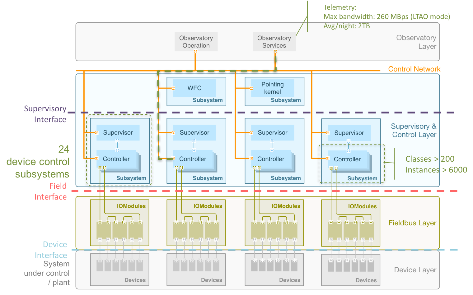
Fig. 3.4 Deployment Architecture#
There are two types of interfaces, shown red in the above Figure:
The Supervisory Interface mediates control of the subsystems and the rest of the SWCS. This includes interfaces with the Common Services, Observatory Operation Components and high-level TCS software subsystems.
The Field Interface mediates the control subsystem and the system under control. This interface is defined in terms of industry protocols when adequate.
The following Figure provides a schematic view of the TCS hardware components deployment and their physical location.
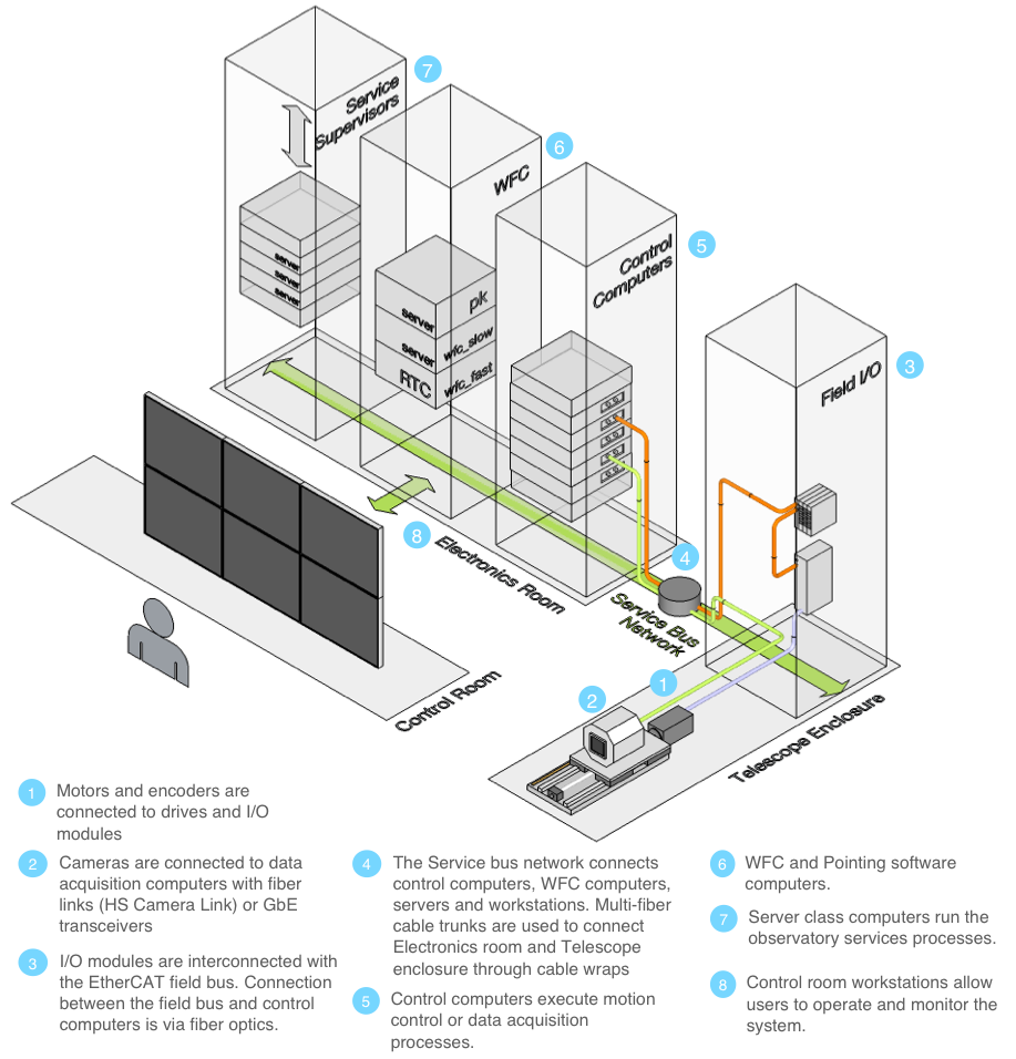
Fig. 3.5 TCS Deployment Schematic#
In the above Figure: (1) Motors and encoders are connected to drives and I/O terminals, (2) Cameras are connected to data acquisition computers with fiber links (e.g. HS Camera Link, GbE or PCIe transceivers), (3) I/O terminals are interconnected with the EtherCAT fieldbus; the connection between the fieldbus and the control computers is also fiber optics, (4) The service bus network connects device control computers, WFCS computers, servers and workstations. Multi-fiber cable trunks are used to connect the electronics room and the telescope enclosure through cable wraps, (5) Device control computers execute motion control and data acquisition processes, (6) WFCS and pointing software computers, (7) Control room workstations allow users to operate and monitor the system.