DCS Reference Architecture#
This chapter gives a description of the GMT Device Control Subsystems (DCS) terminology and architecture, its design philosophy and its main functions. The Software and Controls Architecture and Design provides an extended description of the overall Software and Controls System that illustrates how the different DCS fit in the overall software architecture.
Device Control Subsystems (e.g. primary mirror control system, adaptive secondary control system, instrument control system, etc.) command mechanical degrees of freedom or read from optical and other sensors. Degrees of freedom are represented by a set of state variables that define the observed and desired state of the system and are often updated in an arrangement of nested control loops. Although the primary function of a Device Control Subsystem is the control of hardware devices, an efficient and robust operation requires the development of:
Calibration software that is required to produce error maps or models that allow the control system to achieve the required performance;
Diagnosis software that provides the capability to observe and verify the behavior of some, quite complex, hardware and software subsystems, especially during the commissioning phase;
Safety functions that prevent the engagement of the interlock and safety system, which acts usually in a more ‘dramatic way’; and
Supervision software that coordinates several components or subsystems to guarantee their correct states and that implements fault management strategies that enable the graceful degradation of performance in non-nominal scenarios.
Context#
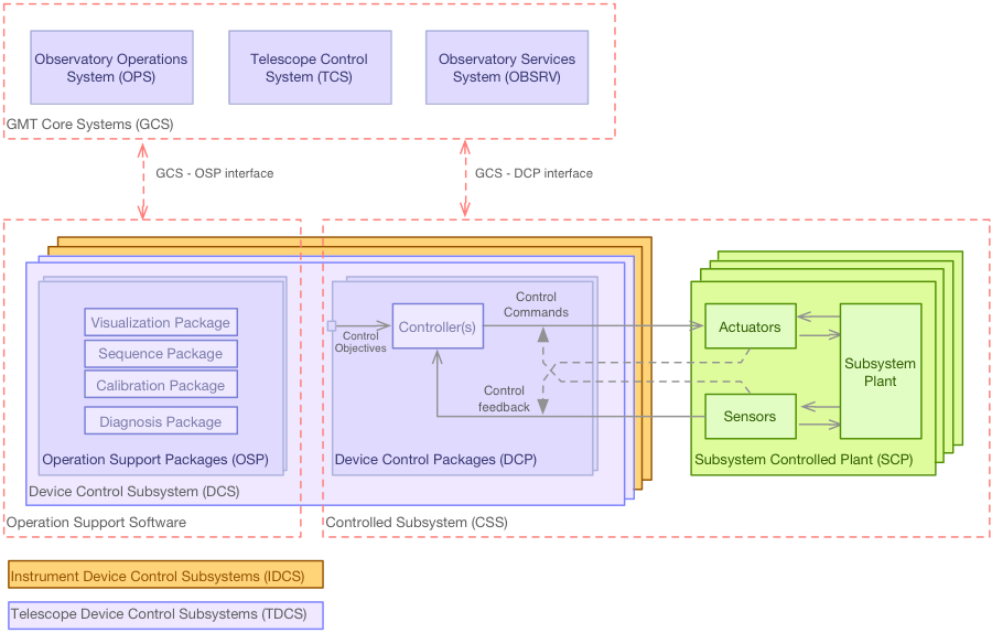
The following diagram extends the previous one to include the DCS components in the context of the overall GMT software:
DCS Context#
The DCS Reference Architecture elements:
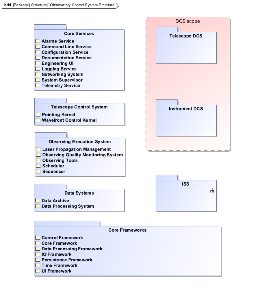
GMT SWC Core Systems
Includes all the hardware and software required to operate the observatory and telescope as a system and to coordinate all the DCSs. It comprises the Observatory Operation System, the Observatory Services System and the global Telescope Control System.
Observing Execution System – Includes all the hardware and software required operate the observatory.
Core Services – Includes common observatory services.
Telescope Control System (TCS) – Includes the system level functions (e.g. wavefront control, pointing) of the telescope control functions.
Controlled Subsystem (CSS)
Control relevant part of a system to achieve the specified control objectives. This includes the control system and the controlled plant. (e.g. M1)
Device Control Subsystem (DCS) – Includes all the hardware and software required to control a Subsystem Controlled Plant (SCP). DCS include a set of Device Control Packages and may include a set of Operation Support Packages (OSP).
Device Control Packages (DCP) – Includes all the software necessary to control a Subsystem Controlled Plant (SCP).
Device Controller – Includes all the software necessary to operate a CSS Device.
Operation Support Packages (OSP) – Includes all the software necessary to operate a CSS integrated with the rest of the observatory.
Subsystem Controlled Plant (SCP) – Physical system, or one of its parts, which is the target of the control problem. Includes sensing and actuating Devices. (e.g. M1 support system). In the State Analysis [ref] terminology the plant is known as system under control.
Additionally two categories of DCS that share the same architectural principles are defined:
Telescope DCS (TDCS) – Collection of DCSs that provide control of telescope and adaptive optics CSS.
Instrument DCS (IDCS) – Collection of DCSs that provide control of a GMT Science Instruments.
Device Control Subsystem Reference Architecture#
Component Architecture#
The design of the GMT software and controls system is based on a distributed component architecture. Components represent the most elementary unit for the purpose of development, testing, integration and reuse. Groups of components can be connected to create composite modules that implement complex functions. Component interfaces are defined using Ports, which can be linked by means of Connectors. For example, connectors are used to (a) integrate standardized reusable control components with a given field bus configuration; (b) connect component responses with user interface components; or (c) connect components with common observatory services. Connectors are specified in the model without making any assumption of the underlying middleware used by the platform-specific implementation.
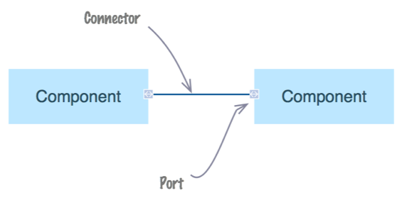
Component, Port, and Connector#
Components, Ports and Connectors are used to model both physical and logical systems. SysML internal block diagrams (ibd) are used to represent how components relate to each other.
The basic components used to model the device control domain are Device Controllers and Supervisors. Device controllers are specialized components that implement the control function of single degree of freedom (e.g. linear position controller) or multiple degrees of freedom that coordinate more elementary ones (e.g. axis group controller). Supervisors implement the high-level interfaces of DCSs and are responsible of the subsystem integrity (e.g. collision avoidance), component configuration, subsystem robustness, component life cycle and subsystem modal transitions amongst other functions.
DCS Product Structure Modeling#
Each DCS is made up of components organized into packages according to their functional affinity or relationships. Examples of packages and their components are shown in the Table below.
Functional Breakdown
Which packages exist in which subsystem depends on the specific functionality (e.g., some subsystems do not require special calibration components, or do not interface with hardware devices). The Table below describes this pattern, split in two categories:
Device Control Packages (DCP) – These packages are included in subsystems that involve the control of optomechanical hardware Devices.
Operation Support Packages (OSP) – These Packages include software components necessary to support health monitoring, automation, and proper operation of a Subsystem. Diagnosis and calibration packages are emphasized early on in the design. This is an area that is often overlooked despite the fact that they may take a significant amount of development effort, especially in the case of complex adaptive optics control subsystems.
Package Name |
Description |
Typical Components |
|---|---|---|
Control Package |
Contains software Components that implement the supervisory and control functions of a Device Control Subsystem (e.g., Mount Control System Control Package). |
Supervisor, Controller |
Data Acquisition |
Contains software Components that implement the supervisory and data acquisition functions of a Detector Control Subsystem (e.g., AGWS Slope Processor Package). Only Subsystems that contain detectors (e.g wavefront sensor, acquisition/guide camera or a science detector) need to provide a Data Acquisition Package. |
Supervisor, Controller, Pipeline |
Hardware Package |
Contains hardware Components in which to deploy the Device Control or Data Acquisition Package software Component and the hardware to interface with the electromechanical Devices. |
Device Control Computer, I/O Module |
Package Name |
Description |
Typical Components |
|---|---|---|
Sequencing Package |
Contains sequence Components necessary for the operation of the Subsystem. |
Sequence |
Diagnosis Package |
Contains software Components necessary to implement diagnosis functions when required. This may involve the development of special control or operation modes. |
Supervisor, Controller, Pipeline, Sequence |
Calibration Package |
Contains software Components necessary for the calibration and characterization of hardware Devices. This may include the development of special control or operation modes. |
Supervisor, Controller, Pipeline, Sequence |
Data Processing Package |
Contains software Components necessary for the calibration and processing of science and WFS detectors. |
Supervisor, Pipeline |
Visualization Package |
Contains software Components that provide custom visualizations necessary for the efficient operation of a given Subsystem (e.g., M1 global status Panel). Note that default engineering Panels are available as part of the Engineering UI service. |
Panel, Widget, |
Observing Tool Plugin Package |
Observing Tool (OT) components provide instrument specific editors that integrate with the GMT Observing Tools to facilitate the specification of instrument specific observation parameters. |
Panel, Widget, Pipeline |
Safety Package |
Contains software/hardware Components that implement Subsystem specific safety functions. These Components often interface with the ISS, but are independent (e.g., M1 safety controller). |
Supervisor, Controller |
Operation Workflows Package |
Contains Components that allow the automation of high- level operation workflows relative to the Subsystem (e.g., unit test workflow, or calibration workflow in case that several sequences and human operations are involved). |
Workflow |
Management Package |
Contains Components that capture the development backlog and the Assembly Integration and Testing plans. |
Plan, Workflow |
The OSP shall interface with the following GCS system functions:
Visualization
Sequencing
Operation workflows
Calibration
Diagnosis
Data processing
Quality monitoring
Safety (through interface ISS)
Instrument Software and Controls Integration#
The GMT instruments software and controls follow the same architectural design as other device control subsystems. Typically an Instrument Device Control Subsystem will include most of the packages described in the Figure on DCS context and will be developed following the standards and rules described in this document. The operation of instrument, telescope and adaptive optics DCSs will be coordinated by the GCS Core Systems (e.g. as operation sequences executed by the Sequencer) in order to execute automated observation or calibration operations. The IDCS data pipeline packages are integrated in the GCS Core Systems (i.e. in the OPS Data Processing System) so quick look and data products management is operated in a uniform way across the observatory. Analogously instrument specific user interface panels and observing tools are integrated in the OPS to ensure consistent and seamless implementation of observatory workflows.
DCS Deployment#
The DCS reference architecture defines a generic design that shall be refined and adapted to the specific CSS. The Figure below gives three examples of possible DCS physical architectures.
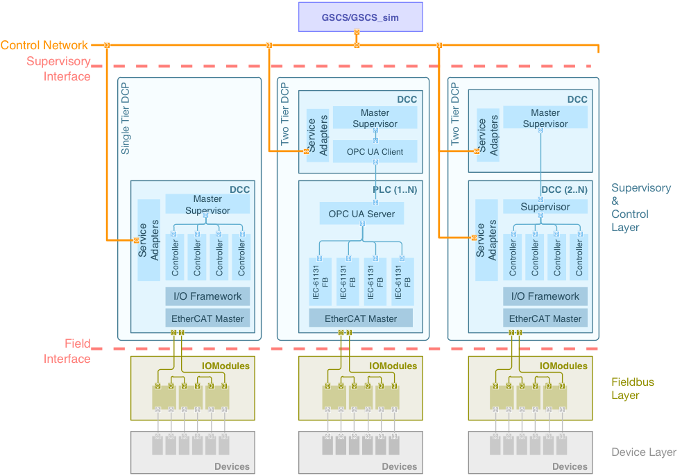
DCP Reference Architecture#
A DCS consists on a set of Device Control Packages (DCP) and a set of Operation Support Packages (OSP).
A DCP consists of one and only one Master Supervisor component for each CSS and one or more Device Control Computers (DCC) hosting Device Controller components interfacing to actuators and sensors via IO Modules. DCP Components communicate with the GCS over the GMT Control Network (GCN). DCP Controllers may be organized in a functional hierarchical manner and can be deployed in several DCCs.
GMTO provides a set of software packages called GMT Software and Controls Development Kit. The GDK includes a set of frameworks and development tools (e.g. code, test and document generation) to be used by DCS developers. The GDK is released at regular intervals (at least once per year, TBD ref to release plan).
The following sections define the requirements that each DCS has to consider in order to meet this architecture.